Stainless Steel Parts, Stainless Steel Components, Stainless Steel Casting & Stainless Steel Stamping

Overview – Comprehensive Stainless Steel Manufacturing Solutions
We are a leading ISO 9001:2015 certified manufacturer and exporter of precision-engineered stainless steel parts, components, fittings, castings, stampings, and machined products, serving global industries for over three decades. Our state-of-the-art manufacturing complex in India integrates advanced CNC machining centers, precision casting foundries, high-capacity forging presses, progressive stamping lines, and automated inspection systems to deliver world-class stainless steel products meeting stringent international standards including ASTM, ASME, DIN, JIS, BS, and IS specifications. Our comprehensive product portfolio encompasses precision CNC machined components, investment castings, sand castings, hot/cold forged parts, progressive stamped components, deep drawn parts, turned components, compression fittings, hydraulic fittings, sanitary fittings, hose barbs, tube fittings, and custom-engineered solutions manufactured from premium stainless steel grades including 304, 304L, 316, 316L, 316Ti, 317L, 321, 410, 420, 430, and duplex alloys (2205, 2507).
Our manufacturing excellence is driven by cutting-edge technology including 5-axis CNC machining centers capable of ±0.005mm tolerances, robotic investment casting lines with ceramic shell molding systems, 3000-ton hydraulic forging presses, high-speed progressive stamping presses operating at 200 strokes/minute, Swiss-type CNC screw machines for micro-precision turning, and fully automated CMM inspection systems ensuring dimensional accuracy verification for every component. Each manufacturing process is supported by advanced heat treatment facilities with controlled atmosphere furnaces, solution annealing systems, aging ovens, and tempering furnaces to achieve optimal mechanical properties and corrosion resistance characteristics required for demanding applications in chemical processing, pharmaceutical, food & beverage, marine, offshore, oil & gas, power generation, automotive, aerospace, and medical device industries worldwide.
Stainless Steel Material Grades – Technical Specifications
Austenitic Stainless Steels (300 Series)
Austenitic stainless steels represent the most widely used category, characterized by face-centered cubic (FCC) crystal structure, excellent corrosion resistance, superior formability, non-magnetic properties, and exceptional weldability. The austenitic microstructure is stabilized by nickel content ranging from 8-20%, providing superior toughness even at cryogenic temperatures down to -196°C. These grades are ideal for applications requiring corrosion resistance, hygiene, aesthetic appearance, and ease of fabrication.
| Grade | UNS | DIN/EN | Key Composition (%) | Key Features | Applications |
|---|---|---|---|---|---|
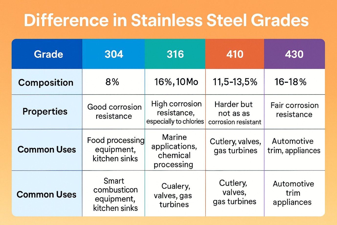
| 304 | S30400 | 1.4301 | Cr: 18-20, Ni: 8-10.5, C: ≤0.08 | General purpose, good corrosion resistance | Architecture, food equipment, chemical tanks |
| 304L | S30403 | 1.4307 | Cr: 18-20, Ni: 8-12, C: ≤0.03 | Low carbon, improved weldability | Welded structures, pharmaceutical equipment |
| 316 | S31600 | 1.4401 | Cr: 16-18, Ni: 10-14, Mo: 2-3, C: ≤0.08 | Superior pitting resistance, marine grade | Marine hardware, chemical processing, medical |
| 316L | S31603 | 1.4404 | Cr: 16-18, Ni: 10-14, Mo: 2-3, C: ≤0.03 | Low carbon variant, best weldability | Pharmaceutical, food, surgical implants |
| 316Ti | S31635 | 1.4571 | Cr: 16-18, Ni: 10-14, Mo: 2-3, Ti: 5×C min | Titanium stabilized, prevents sensitization | High-temperature applications, petrochemical |
| 317L | S31703 | 1.4438 | Cr: 18-20, Ni: 11-15, Mo: 3-4, C: ≤0.03 | Higher molybdenum, enhanced corrosion resistance | Pulp & paper, chemical processing |
| 321 | S32100 | 1.4541 | Cr: 17-19, Ni: 9-12, Ti: 5×C min | Titanium stabilized, high temperature strength | Exhaust systems, furnace parts, jet engines |
Martensitic Stainless Steels (400 Series)
Martensitic stainless steels are characterized by body-centered tetragonal (BCT) crystal structure, magnetic properties, high strength, moderate corrosion resistance, and excellent hardenability through heat treatment. These grades contain 11.5-18% chromium with higher carbon content (0.15-1.2%) enabling transformation hardening to achieve hardness levels of 40-60 HRC depending on grade and heat treatment parameters.
| Grade | UNS | DIN/EN | Key Composition (%) | Hardness Potential | Applications |
|---|---|---|---|---|---|
| 410 | S41000 | 1.4006 | Cr: 11.5-13.5, C: ≤0.15 | 40 HRC (hardened) | Valve parts, pump shafts, fasteners |
| 420 | S42000 | 1.4021 | Cr: 12-14, C: 0.15 min | 50-55 HRC (hardened) | Cutlery, surgical instruments, bearings |
| 440C | S44004 | 1.4125 | Cr: 16-18, C: 0.95-1.20 | 58-60 HRC (hardened) | Ball bearings, valve seats, precision components |
Ferritic Stainless Steels (400 Series)
Ferritic stainless steels possess body-centered cubic (BCC) crystal structure, magnetic properties, good corrosion resistance in mild environments, excellent resistance to stress corrosion cracking, and lower cost compared to austenitic grades. These grades contain 10.5-30% chromium without nickel, making them economical alternatives for applications not requiring the premium performance of austenitic grades.
| Grade | UNS | Key Composition (%) | Characteristics |
|---|---|---|---|
| 430 | S43000 | Cr: 16-18, C: ≤0.12 | General purpose, automotive trim, appliances |
| 409 | S40900 | Cr: 10.5-11.75, C: ≤0.08 | Lowest cost grade, automotive exhaust systems |
Duplex Stainless Steels
Duplex stainless steels feature approximately 50% austenite and 50% ferrite microstructure, combining the beneficial properties of both phases. These grades offer twice the yield strength of austenitic stainless steels, superior resistance to stress corrosion cracking, excellent pitting and crevice corrosion resistance, and lower nickel content reducing material costs. The balanced microstructure provides unique advantages for demanding applications in offshore, oil & gas, chemical processing, and desalination industries.
| Grade | UNS | PREN* | Key Features | Applications |
|---|---|---|---|---|
| 2205 | S31803/S32205 | 35-38 | Most common duplex, balanced properties | Offshore platforms, heat exchangers, chemical tanks |
| 2507 | S32750 | 42-45 | Super duplex, superior corrosion resistance | Subsea equipment, desalination, severe chloride environments |
*PREN = Pitting Resistance Equivalent Number = %Cr + 3.3×%Mo + 16×%N
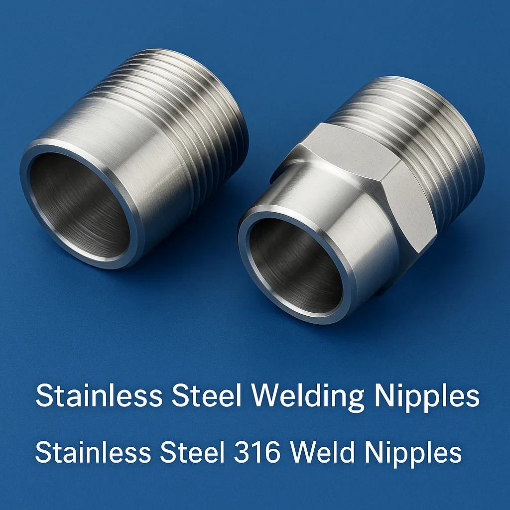
Stainless Steel 316 Fittings
Stainless Steel 316 fittings represent the industry benchmark for corrosion-resistant pipe connection solutions, specifically engineered for applications demanding exceptional resistance to chlorides, sulfuric acids, bromides, iodides, and marine environments. The 316 grade composition featuring 16-18% chromium, 10-14% nickel, and critically 2-3% molybdenum content provides enhanced resistance to pitting corrosion (ASTM G48 Method A rating >24 hours), crevice corrosion, and stress corrosion cracking compared to standard 304 grade materials. Our comprehensive manufacturing portfolio encompasses socket weld fittings, threaded (NPT, BSP, metric) fittings, butt weld fittings, compression fittings, union fittings, sanitary tri-clamp fittings, hydraulic fittings (ORFS, JIC 37°, SAE), pneumatic fittings, instrumentation fittings, and specialty custom fittings manufactured to rigorous ASME B16.11, ASME B16.9, MSS SP-79, MSS SP-83, and DIN 2353 standards with pressure ratings from Class 3000 (3000 PSI) to Class 9000 (9000 PSI) depending on size, configuration, and operating temperature parameters.
Manufacturing Excellence and Process Control
Our SS 316 fitting production utilizes certified raw materials conforming to ASTM A182 F316/F316L, ASTM A351 CF8M (cast), and ASTM A479 316/316L (bar stock) specifications, sourced exclusively from approved mills with complete mill test certificates (MTC) per EN 10204 Type 3.1 documentation. The manufacturing process begins with precision hot forging operations using 1000-3000 ton hydraulic presses with induction heating systems maintaining optimal forging temperatures of 1050-1200°C, followed by controlled cooling to achieve fine-grained microstructure. Forged blanks undergo solution annealing heat treatment at 1038-1149°C (1900-2100°F) in controlled atmosphere furnaces, followed by rapid water quenching to dissolve chromium carbides and optimize corrosion resistance properties. Secondary machining operations employ multi-axis CNC machining centers with live tooling capabilities achieving dimensional tolerances of ±0.025mm (±0.001″) for critical sealing surfaces, thread geometries, and connection interfaces. Final processing includes deburring, passivation per ASTM A380/A967 standards, and optional electropolishing treatments achieving surface roughness values of Ra 0.4 micrometers or better for sanitary and ultra-high-purity applications.
Technical Specifications and Performance Characteristics
Mechanical Properties (Annealed Condition)
- Tensile Strength: 515-620 MPa (75-90 ksi)
- Yield Strength (0.2% offset): 205-310 MPa (30-45 ksi)
- Elongation in 50mm: 35% minimum
- Hardness: 95 HRB maximum (≤217 HBW)
- Impact Toughness: >100 Joules at room temperature
Corrosion Resistance Performance
- Pitting Resistance: PREN ≥ 25-26
- Critical Pitting Temperature: >15°C in 6% FeCl₃
- Chloride SCC Threshold: >200 ppm at 50°C
- Sulfuric Acid Resistance: Excellent up to 10% concentration
- Seawater Corrosion Rate: <0.1 mm/year
Physical Properties
- Density: 8.0 g/cm³ (0.289 lb/in³)
- Melting Range: 1371-1399°C (2500-2550°F)
- Thermal Conductivity: 16.3 W/m·K at 100°C
- Coefficient of Thermal Expansion: 16.0 μm/m·K (0-100°C)
- Electrical Resistivity: 74 μΩ·cm at 20°C
- Magnetic Permeability: <1.02 (essentially non-magnetic)
Pressure-Temperature Ratings
- Class 3000 (1/8″-2″): Up to 6000 PSI @ -20°F to 100°F
- Class 6000 (1/8″-1-1/2″): Up to 6000 PSI @ 100°F
- Working Temperature Range: -425°F to +800°F (-254°C to +427°C)
- Continuous Service: Up to 400°C (752°F)
- Cryogenic Applications: Down to -196°C (LNG service)
Fitting Types and Configurations
Socket Weld Fittings (ASME B16.11)
Socket weld fittings feature recessed sockets with precise bore dimensions matching standard pipe OD tolerances, designed for permanent welding connections in sizes 1/8″ through 4″ NPS. These fittings provide superior fatigue resistance compared to threaded connections and are ideal for high-pressure, high-cycle applications in power generation, chemical processing, and oil & gas industries. Socket depth typically equals pipe wall thickness plus 1.6mm (1/16″) expansion gap to prevent cracking during welding thermal cycles. Available in Class 3000, 6000, and 9000 pressure ratings with full penetration weld requirements per ASME B31.3 piping code.
Threaded Fittings (NPT, BSP, Metric)
Precision CNC thread-milled fittings offering removable connections for sizes 1/8″ through 4″ with NPT (National Pipe Taper per ASME B1.20.1), BSPT (British Standard Pipe Taper per ISO 7-1), and metric ISO 228-1 parallel thread configurations. Thread quality verified using precision GO/NO-GO gauges with 6g tolerance class for external threads and 6H for internal threads. Threaded fittings require thread sealant or PTFE tape application and are rated for lower cyclic loads compared to welded connections but offer field serviceability advantages. Pressure ratings range from 1000-6000 PSI based on size, with derating factors applied for elevated temperature service per ASME B16.34 guidelines.
Butt Weld Fittings (ASME B16.9)
Seamless and welded butt weld fittings manufactured from pipe or plate material, available in long radius (LR) and short radius (SR) configurations for sizes 1/2″ through 48″ NPS. These fittings feature beveled ends with 37.5° ±2.5° angle and 1.6mm (1/16″) root face for GTAW root pass welding followed by SMAW or GMAW fill passes. Long radius elbows with centerline radius equal to 1.5D provide lower pressure drop and reduced erosion compared to short radius fittings. Manufacturing standards ensure wall thickness matching schedule 10S through XXS (Schedule 160) pipe specifications with dimensional tolerances per MSS SP-43 for wrought fittings and MSS SP-75 for cast fittings.
Compression Fittings (Instrumentation Grade)
High-performance compression fittings utilizing double ferrule sealing technology (front ferrule and back ferrule) providing vibration-resistant, leak-tight seals for pressures up to 20,000 PSI in smaller tube sizes (1/16″ to 1″ OD). The compression mechanism creates controlled plastic deformation of ferrules against tube OD surface, forming annular seal with redundancy factor for gas-tight service in instrumentation, analytical equipment, and process sampling systems. Compatible with tubing per ASTM A269, A213, and A511 specifications with surface finish requirements of Ra ≤0.8 micrometers. Installation torque values range from 1/4 turn to full turn beyond finger-tight depending on size, following manufacturer-specific installation procedures for optimal performance.
Sanitary Tri-Clamp Fittings (3-A Standards)
Hygienic fittings designed for pharmaceutical, food, beverage, and biotechnology applications featuring quick-disconnect tri-clamp connections with elastomeric gaskets (EPDM, silicone, Viton®) providing tool-free assembly/disassembly for CIP (clean-in-place) and SIP (sterilize-in-place) operations. Internal surfaces are electropolished to achieve Ra ≤0.4 micrometers (15 microinches) surface roughness eliminating bacterial harboring sites and facilitating complete drainage. Manufactured from 316L stainless steel per ASTM A270 specifications with seamless construction, crevice-free design, and self-draining orientation capability. Pressure ratings typically 150 PSI at 300°F with full vacuum capability. Dimensional standards include ISO 2852 (metric) and ASME BPE (imperial) with ferrule sizes from 1/2″ through 12″ nominal.
| Fitting Type | Size Range | Pressure Rating | Standards | Key Applications |
|---|---|---|---|---|
| Socket Weld Elbows 90°/45° | 1/8″ – 4″ | 3000-9000 PSI | ASME B16.11 | High-pressure piping systems |
| Socket Weld Tees | 1/8″ – 4″ | 3000-9000 PSI | ASME B16.11 | Branch connections, manifolds |
| Socket Weld Couplings | 1/8″ – 4″ | 3000-9000 PSI | ASME B16.11 | Pipe joining, repair |
| Threaded Elbows NPT | 1/8″ – 4″ | 1000-6000 PSI | ASME B16.11, B1.20.1 | Removable connections |
| Butt Weld Elbows LR | 1/2″ – 48″ | Schedule dependent | ASME B16.9 | Large diameter piping |
| Butt Weld Reducers | 1/2″ – 48″ | Schedule dependent | ASME B16.9 | Size transitions |
| Compression Fittings | 1/16″ – 1″ OD | Up to 20,000 PSI | ASME B31.3 | Instrumentation tubing |
| Tri-Clamp Ferrules | 1/2″ – 12″ | 150 PSI | ASME BPE, ISO 2852 | Sanitary process equipment |
| Weld Neck Flanges | 1/2″ – 48″ | 150-2500# | ASME B16.5, B16.47 | Equipment connections |
| Hydraulic Adapters ORFS | 1/4″ – 2″ | 3000-6000 PSI | SAE J1453 | Mobile hydraulics, marine |
Stainless Steel 316 Machined Components
Precision CNC machined stainless steel 316 components represent custom-engineered solutions for applications requiring complex geometries, tight dimensional tolerances (±0.005mm to ±0.025mm), superior surface finishes (Ra 0.1 to 3.2 micrometers), and consistent mechanical properties unattainable through casting or forming processes. Our advanced machining capabilities encompass 3-axis, 4-axis, and 5-axis CNC vertical/horizontal machining centers with work envelope capacities from 500mm to 2000mm, equipped with high-speed spindles (12,000-24,000 RPM), automatic tool changers (30-60 position magazines), through-spindle coolant delivery systems, and in-process measurement probes ensuring first-article and production part dimensional verification. Typical machined components include valve bodies, pump housings, manifold blocks, instrumentation housings, sensor brackets, custom flanges, bearing housings, actuator components, gearbox housings, hydraulic blocks, pneumatic manifolds, medical instrument components, and aerospace structural parts manufactured from certified bar stock, plate, and forging materials per ASTM A479, A276, and A182 specifications.
CNC Machining Processes and Capabilities
Multi-Axis CNC Milling
Our vertical and horizontal CNC machining centers perform precision milling operations including face milling, peripheral milling, pocket milling, contour milling, and cavity milling with cutting tool materials optimized for stainless steel machining (carbide inserts with TiAlN/AlTiN coatings, CBN tools for hardened materials). Typical cutting parameters for 316 stainless steel include surface speeds of 60-120 m/min for roughing operations and 120-180 m/min for finishing operations, with feed rates of 0.1-0.4 mm/tooth and depth of cut ranging from 2-8mm for roughing and 0.2-1mm for finishing passes. High-pressure coolant delivery (70-150 bar) enhances chip evacuation and tool life when machining stainless steel’s work-hardening characteristics.
CNC Turning and Swiss Machining
CNC lathes and Swiss-type automatic screw machines produce precision turned components including shafts, pins, bushings, sleeves, spacers, and complex rotational parts with diameter ranges from 1mm to 500mm and length capacities up to 1500mm. Swiss machining excels for small diameter parts (0.5mm to 32mm) requiring length-to-diameter ratios exceeding 10:1, utilizing guide bushing support to minimize deflection during machining operations. Typical turning operations include facing, OD/ID turning, threading (60° V-threads, ACME, buttress), grooving, parting, drilling, reaming, boring, and knurling with surface finish capabilities down to Ra 0.4 micrometers using wiper inserts and optimized cutting parameters.
Drilling, Tapping, and Boring
Precision hole-making operations employ solid carbide drills, indexable insert drills, and gundrills for deep-hole applications achieving diameter tolerances of IT6 to IT8 (±0.008mm to ±0.025mm for 10mm holes) and position tolerances within ±0.05mm. Tapping operations produce internal threads from M2 through M64 with tapping accuracy class 6H utilizing synchronous rigid tapping functions ensuring precise thread geometry. Boring operations with adjustable boring heads achieve IT7 hole tolerances and cylindricity tolerances of 0.005mm while maintaining concentricity to external features within 0.02mm TIR.
Quality Assurance and Inspection
Every machined component undergoes comprehensive dimensional inspection utilizing CMM (Coordinate Measuring Machine) systems with accuracy of ±(2.5 + L/300) micrometers, optical comparators with 50X magnification capability, laser micrometers for non-contact measurement, surface roughness testers, and precision measuring instruments including micrometers (±0.001mm), height gauges, bore gauges, and thread gauges. First article inspection reports (FAIR) per AS9102 standards document complete dimensional verification, material certification, and process validation. Statistical process control (SPC) monitoring tracks critical dimensions throughout production runs ensuring Cpk values >1.67 (6 sigma capability) for key characteristics.
Machining Capabilities Summary:
- Dimensional Tolerances: ±0.005mm to ±0.025mm (general), ±0.002mm (critical features)
- Surface Finish: Ra 0.1 to 3.2 micrometers (as-machined), <0.05 Ra (lapped surfaces)
- Position Tolerance: ±0.025mm to ±0.05mm (drilled holes)
- Concentricity: 0.01mm to 0.05mm TIR (turned features)
- Flatness: 0.01mm to 0.05mm per 100mm length
- Parallelism: 0.02mm to 0.05mm per 100mm length
- Thread Accuracy: 6H class (internal), 6g class (external)
- Minimum Wall Thickness: 0.3mm (depending on geometry)
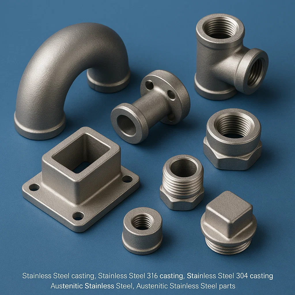
Stainless Steel Casting
Stainless steel precision casting encompasses investment casting (lost-wax process), sand casting, and centrifugal casting technologies producing complex geometrical components with near-net-shape accuracy, reduced material waste, excellent surface finish, and cost-effective manufacturing for medium to large production quantities. Our integrated casting foundry capabilities handle component weights from 10 grams to 500 kilograms, wall thickness ranges of 2mm to 100mm, and dimensional tolerances achievable within ±0.3mm to ±1.5mm depending on casting size and complexity per ISO 8062 CT7 to CT10 casting tolerance grades. Investment casting particularly excels for intricate components requiring complex internal passages, undercuts, fine surface details, and thin-wall sections (minimum 1.5mm) unattainable through machining or forging processes. Common cast stainless steel grades include CF8 (304 equivalent), CF8M (316 equivalent), CF3 (304L equivalent), CF3M (316L equivalent), CD4MCu (duplex), and precipitation hardening grades like 17-4PH (J92600) for applications demanding high strength combined with moderate corrosion resistance.
Investment Casting Process (Lost-Wax Precision Casting)
Investment casting delivers superior surface finish (Ra 1.6-6.3 micrometers as-cast) and dimensional accuracy with minimal draft angles (0-1°) required compared to sand casting (3-5° draft). The process begins with injection molding of wax patterns using specialized wax compounds (melting point 60-70°C) incorporating pattern shrinkage allowances of 1.2-2.0% depending on alloy composition. Multiple wax patterns are assembled onto a common runner system (tree assembly) accommodating 10-200 individual patterns depending on size. The wax tree undergoes sequential ceramic shell building through repeated dipping in ceramic slurry (colloidal silica binder with fine zircon or fused silica flour) followed by stucco coating application (coarse ceramic particles) building shell thickness of 6-12mm over 7-10 coating cycles. After shell drying and curing, the wax is removed via steam autoclave (dewaxing), leaving a precise ceramic mold cavity. The ceramic shells undergo high-temperature burnout firing at 900-1050°C to achieve full strength and remove residual wax/organic contaminants before metal pouring operations.
Melting and Pouring Operations
Stainless steel melting utilizes induction furnaces (coreless or channel type) with capacities from 100kg to 5000kg providing precise temperature control (±10°C), rapid melting, controlled atmosphere conditions, and minimal contamination. The molten metal achieves pouring temperatures of 1480-1650°C depending on alloy grade and section thickness requirements. Gravity pouring, tilt pouring, or vacuum-assisted pouring techniques fill the ceramic molds with superheat control critical for thin-wall castings requiring extended fluidity. After solidification (cooling time: 2-24 hours depending on mass), the ceramic shells are removed via mechanical knockout, vibratory shakeout, or high-pressure water blasting, revealing the finished castings complete with gating system.
Heat Treatment and Finishing
Cast stainless steel components undergo solution annealing heat treatment at temperatures specific to grade: CF8/CF8M at 1040-1150°C, duplex grades at 1020-1100°C, and precipitation hardening grades per specific aging cycles (480-620°C for 1-4 hours). Austenitic grades require rapid cooling (water quenching or forced air cooling) to prevent chromium carbide precipitation in the 427-816°C sensitization temperature range. Post-heat treatment operations include cutoff of gating systems using abrasive cutting, surface grinding to remove casting defects, shot blasting or tumbling for surface cleaning (Ra 3.2-6.3 micrometers), and final machining of critical dimensions, sealing faces, and threaded connections.
Sand Casting Process
Sand casting accommodates larger component production (10kg to 5000kg+) with lower tooling costs compared to investment casting but produces rougher surface finishes (Ra 12.5-50 micrometers) and looser dimensional tolerances (CT10-CT13 per ISO 8062). Green sand molding utilizes silica sand mixed with bentonite clay (5-8%) and water (3-5%) providing economical, recyclable molding material suitable for ferrous and non-ferrous casting. Resin-bonded sand systems (furan, phenolic, sodium silicate) offer improved dimensional accuracy and surface finish for complex molds requiring cores. Pattern equipment fabricated from wood, plastic, or aluminum incorporates draft angles (3-5°), machining allowances (3-10mm per side), and shrinkage allowances (1.8-2.5% for stainless steel). Common sand cast stainless steel applications include pump housings, valve bodies, impellers, marine hardware, architectural components, and industrial machinery parts where near-net-shape casting reduces subsequent machining costs.
Material Grades and Specifications
| Cast Grade | ASTM Spec | Wrought Equivalent | Key Properties | Typical Applications |
|---|---|---|---|---|
| CF8 | A351 CF8 | 304 | Tensile: 485 MPa min, Yield: 205 MPa min, Elongation: 35% min | Pump casings, valve bodies, food equipment |
| CF8M | A351 CF8M | 316 | Tensile: 485 MPa min, Yield: 205 MPa min, Mo: 2-3% | Chemical pumps, marine hardware, pharmaceutical |
| CF3 | A351 CF3 | 304L | Low carbon (0.03% max), improved weldability | Welded structures, cryogenic service |
| CF3M | A351 CF3M | 316L | Low carbon + Mo, superior corrosion resistance | Petrochemical equipment, offshore applications |
| CD4MCu | A890 Gr 1A/1B | Duplex 2205 | Tensile: 655 MPa min, Yield: 450 MPa min, Cu-enhanced | High-strength marine components, pumps |
| 17-4PH | A747 CB7Cu-1 | 17-4 PH (S17400) | Age-hardenable to 35-45 HRC, high strength | Aerospace components, high-stress applications |
| CN7M | A351 CN7M | AL-6XN (Super austenitic) | High Mo+Ni, superior pitting resistance | Severe corrosion environments |
Casting Quality Standards and Testing
Non-Destructive Testing (NDT)
- Visual Inspection: 100% per ASTM E165
- Liquid Penetrant Testing: Per ASTM E1417
- Magnetic Particle Testing: Per ASTM E1444 (ferritic grades)
- Radiographic Testing: Per ASTM E94 (critical castings)
- Ultrasonic Testing: Per ASTM E2375 (thick sections)
Mechanical Testing
- Tensile Testing: Per ASTM A370, E8
- Hardness Testing: Brinell, Rockwell per ASTM E10, E18
- Impact Testing: Charpy V-notch per ASTM E23
- Proof Load Testing: Hydrostatic pressure testing
Chemical Analysis
- Spectroscopic Analysis: OES per ASTM E1086
- Carbon/Sulfur Analysis: Combustion method
- Nitrogen Analysis: Inert gas fusion
- Ferrite Content: Ferritescope measurement
Dimensional Inspection
- CMM Inspection: Critical dimensions
- Template Verification: Complex contours
- Wall Thickness: Ultrasonic measurement
- Straightness/Flatness: Surface plate measurement
Stainless Steel Casting Foundry
Our ISO 9001:2015 certified stainless steel casting foundry represents a fully integrated manufacturing facility encompassing pattern making, molding, melting, pouring, heat treatment, machining, and quality testing operations under one roof, ensuring complete process control, reduced lead times, and consistent quality throughout the production cycle. The foundry infrastructure includes separate melting departments for austenitic and martensitic grades preventing cross-contamination, automated molding lines for high-volume production, manual molding stations for prototype and low-volume work, multiple heat treatment furnaces with controlled atmosphere capabilities, extensive machining equipment for casting finishing operations, and comprehensive NDT laboratory facilities equipped with radiographic testing equipment, ultrasonic testing systems, penetrant testing stations, and dimensional inspection instruments. Annual production capacity exceeds 2500 metric tons of finished cast components serving global customers across aerospace, defense, marine, oil & gas, power generation, mining, and general industrial sectors.
Foundry Equipment and Infrastructure
Melting Department
Our melting operations utilize medium frequency induction furnaces ranging from 500kg to 3000kg capacity, operating at frequencies of 500Hz to 2500Hz providing rapid melting, precise temperature control within ±5°C, reduced oxidation losses, and minimal alloy segregation. Separate melting units for austenitic stainless steels (304, 316 families) and martensitic/precipitation hardening grades prevent contamination concerns. Ladle preheating systems maintain ladle temperatures of 600-800°C minimizing thermal shock and temperature drop during pouring operations. Argon oxygen decarburization (AOD) refining capability allows production of ultra-low carbon grades (CF3, CF3M) and tight compositional control for critical applications. Spectrographic analysis equipment enables real-time composition verification before pouring with adjustments possible via alloying additions.
Molding and Coremaking
Investment casting shell building station features automated wax injector machines producing consistent wax patterns with ±0.15mm dimensional repeatability, robotic dipping systems for shell building ensuring uniform coating thickness, and controlled environment curing rooms (20-25°C, 40-60% RH) optimizing shell development. Sand casting operations include automated green sand molding lines with compaction ratios of 2.5-3.0:1 achieving uniform density, resin-bonded sand mixers for chemically bonded molds, and core-blowing machines producing complex sand cores for internal passages and hollow sections. Pattern equipment fabricated in-house from aluminum casting alloys or machined urethane provides rapid turnaround for prototype and custom production requirements.
Heat Treatment Facilities
Multiple controlled atmosphere furnaces accommodate batch sizes from 100kg to 5000kg with temperature uniformity within ±10°C throughout the working zone. Furnace atmospheres include nitrogen-hydrogen mixtures for bright annealing, protective nitrogen atmospheres preventing oxidation, and vacuum furnaces for critical aerospace components requiring exceptional surface cleanliness. Quench tanks utilize water, polymer solutions, or forced air cooling systems providing controlled cooling rates from solution annealing temperatures. Aging furnaces for precipitation hardening grades maintain precise temperature control (±3°C) over extended holding periods (1-4 hours) ensuring consistent mechanical properties.
Quality Management System
Our foundry operates under ISO 9001:2015 certified quality management system with additional approvals including ISO 14001 environmental management, OHSAS 18001 occupational health & safety, and customer-specific quality certifications (Nadcap, AS9100, API Q1) depending on application requirements. Process documentation includes detailed casting procedures, material specifications, heat treatment cycles, inspection criteria, and handling procedures ensuring complete traceability from raw material receipt through final shipment. Every casting receives unique identification marking via vibratory engraving, electro-chemical etching, or cast-in identification allowing lifetime traceability to material heat lot, pouring date, heat treatment batch, and inspection records.
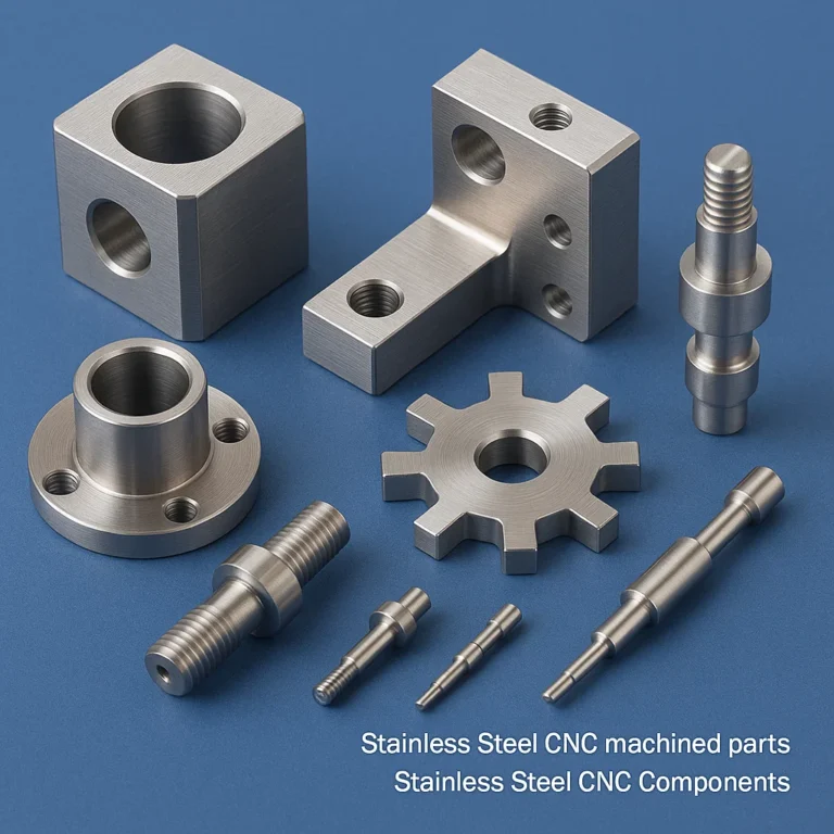
Stainless Steel CNC Parts & CNC Machined Components
Stainless steel CNC machined parts represent the pinnacle of precision manufacturing, combining advanced computer numerical control technology with specialized cutting tools, optimal machining parameters, and rigorous quality control to produce components meeting aerospace (AS9100), medical (ISO 13485), automotive (IATF 16949), and industrial quality standards. Our comprehensive CNC machining capabilities span 3-axis vertical machining centers for prismatic components, 4-axis horizontal machining centers for complex multi-sided parts, 5-axis simultaneous machining centers for sculptured surfaces and compound angle features, CNC turning centers for rotational components, Swiss-type CNC screw machines for high-precision small diameter parts, multi-tasking machining centers combining turning and milling operations, and EDM (electrical discharge machining) for complex cavities and hardened materials. Component complexity ranges from simple bushings and spacers to intricate manifold blocks with cross-drilled passages, valve bodies with complex internal cavities, medical instrument components requiring biocompatibility, aerospace structural brackets with weight-optimized designs, and custom-engineered solutions manufactured in quantities from prototype single pieces to production runs exceeding 100,000 pieces annually.
Advanced CNC Machining Technologies
5-Axis Simultaneous Machining
Our 5-axis CNC machining centers provide simultaneous control of three linear axes (X, Y, Z) plus two rotational axes (A, B or A, C configurations) enabling machining of complex freeform surfaces, compound angle features, and multi-sided components in single setup operations eliminating multiple workholding operations and improving dimensional accuracy through reduced setup errors. Typical applications include aerospace turbine components, medical implants with complex anatomical geometries, impellers with twisted vane profiles, and mold/die components requiring sculptured surfaces. Machine work envelopes range from 500mm × 500mm × 500mm for smaller components to 1500mm × 1500mm × 1000mm for larger structural parts, with rotary table indexing accuracies of ±3 arc-seconds ensuring precise angular positioning.
High-Speed Machining (HSM)
High-speed machining strategies employ spindle speeds of 12,000-40,000 RPM, rapid traverse rates of 30-60 m/min, and optimized tool paths utilizing trochoidal milling, dynamic milling, and constant engagement techniques to maintain consistent chip loads while maximizing material removal rates and minimizing cycle times. HSM particularly benefits thin-wall component machining (wall thickness 0.5-2mm) where reduced cutting forces prevent workpiece deflection and vibration. Tool systems utilize balanced holder assemblies (G2.5 balance grade at 25,000 RPM), shrink-fit holders providing superior runout performance (<0.003mm), and hydraulic expansion holders for maximum rigidity. Cutting tool geometries feature sharp cutting edges, polished rake faces, and specialized coatings (AlTiN, TiAlN, diamond-like carbon) optimized for stainless steel’s work-hardening characteristics.
Multi-Tasking Machining Centers
Mill-turn machining centers integrate CNC lathe and machining center capabilities within single machine platforms featuring main spindle (C-axis positioning), sub-spindle for part transfer and backside operations, rotating tool turrets with live tooling (powered milling cutters), and Y-axis capability enabling off-centerline milling operations. These machines excel for complex rotational components requiring milling features (cross-holes, flats, slots) combined with turning operations (OD/ID machining, threading, grooving) completing parts in one chucking thereby eliminating workholding errors and reducing cycle times by 40-60% compared to sequential turning and milling operations. Typical applications include hydraulic valve spools, aerospace shaft assemblies, medical bone screws, and instrumentation components.
Material-Specific Machining Parameters
| Operation | 304/304L Parameters | 316/316L Parameters | Duplex 2205 Parameters | 410/420 Parameters |
|---|---|---|---|---|
| Turning (Roughing) | Vc: 80-120 m/min f: 0.2-0.4 mm/rev ap: 2-5mm | Vc: 70-100 m/min f: 0.15-0.35 mm/rev ap: 2-4mm | Vc: 60-90 m/min f: 0.15-0.3 mm/rev ap: 1.5-3mm | Vc: 90-140 m/min f: 0.2-0.4 mm/rev ap: 2-5mm |
| Turning (Finishing) | Vc: 120-180 m/min f: 0.05-0.15 mm/rev ap: 0.2-1mm | Vc: 100-150 m/min f: 0.05-0.12 mm/rev ap: 0.2-0.8mm | Vc: 80-120 m/min f: 0.05-0.12 mm/rev ap: 0.2-0.8mm | Vc: 130-200 m/min f: 0.05-0.15 mm/rev ap: 0.2-1mm |
| Milling (Roughing) | Vc: 80-120 m/min fz: 0.1-0.25 mm/tooth ap/ae: 3-8mm | Vc: 70-100 m/min fz: 0.08-0.2 mm/tooth ap/ae: 2-6mm | Vc: 50-80 m/min fz: 0.08-0.18 mm/tooth ap/ae: 2-5mm | Vc: 90-140 m/min fz: 0.1-0.25 mm/tooth ap/ae: 3-8mm |
| Milling (Finishing) | Vc: 120-200 m/min fz: 0.05-0.15 mm/tooth ap/ae: 0.3-2mm | Vc: 100-160 m/min fz: 0.05-0.12 mm/tooth ap/ae: 0.3-1.5mm | Vc: 80-120 m/min fz: 0.05-0.12 mm/tooth ap/ae: 0.3-1.5mm | Vc: 130-220 m/min fz: 0.05-0.15 mm/tooth ap/ae: 0.3-2mm |
| Drilling | Vc: 40-80 m/min f: 0.1-0.3 mm/rev | Vc: 35-70 m/min f: 0.08-0.25 mm/rev | Vc: 30-60 m/min f: 0.08-0.2 mm/rev | Vc: 50-100 m/min f: 0.1-0.3 mm/rev |
Note: Vc = cutting speed, f = feed rate, fz = feed per tooth, ap = axial depth of cut, ae = radial depth of cut
Machining Challenges and Solutions
Work Hardening Mitigation
Stainless steel alloys, particularly austenitic grades, exhibit significant work hardening during machining operations where plastic deformation increases surface hardness from 150 HV to over 300 HV in the affected zone. This phenomenon necessitates sharp cutting edges (hone radius <0.015mm), positive rake angle geometries (12-15° rake angle), sufficient chip load maintenance (avoiding rubbing), and progressive tool paths preventing tool re-engagement with work-hardened surfaces. Interrupted cuts and excessive dwelling at feed hold positions must be avoided to prevent work hardening that dramatically accelerates tool wear.
Built-Up Edge (BUE) Prevention
Built-up edge formation occurs when stainless steel workpiece material welds to cutting tool surfaces under high temperature and pressure conditions, degrading surface finish and causing irregular tool wear. Prevention strategies include maintaining adequate cutting speeds generating sufficient heat to prevent cold welding, application of high-pressure coolant (50-100 bar) directly at cutting interface, utilization of coated carbide tools with low affinity for stainless steel, and selection of positive rake angle geometries reducing cutting forces and temperatures. Surface speeds below 40 m/min particularly prone to BUE formation should be avoided.
Chip Control and Evacuation
Stainless steel produces stringy, continuous chips that can cause machine downtime through chip wrapping around cutting tools, workpieces, and machine components. Effective chip control employs chipbreaker geometries on cutting inserts creating controlled chip curl radii of 3-8mm, high-pressure coolant delivery (70-150 bar through-spindle coolant) breaking chips into manageable segments, optimal chip evacuation via properly oriented machine spindles and work envelopes, and automated chip conveyors removing chips from machining zone. Peck drilling cycles with frequent retraction help break chips during deep-hole drilling operations.
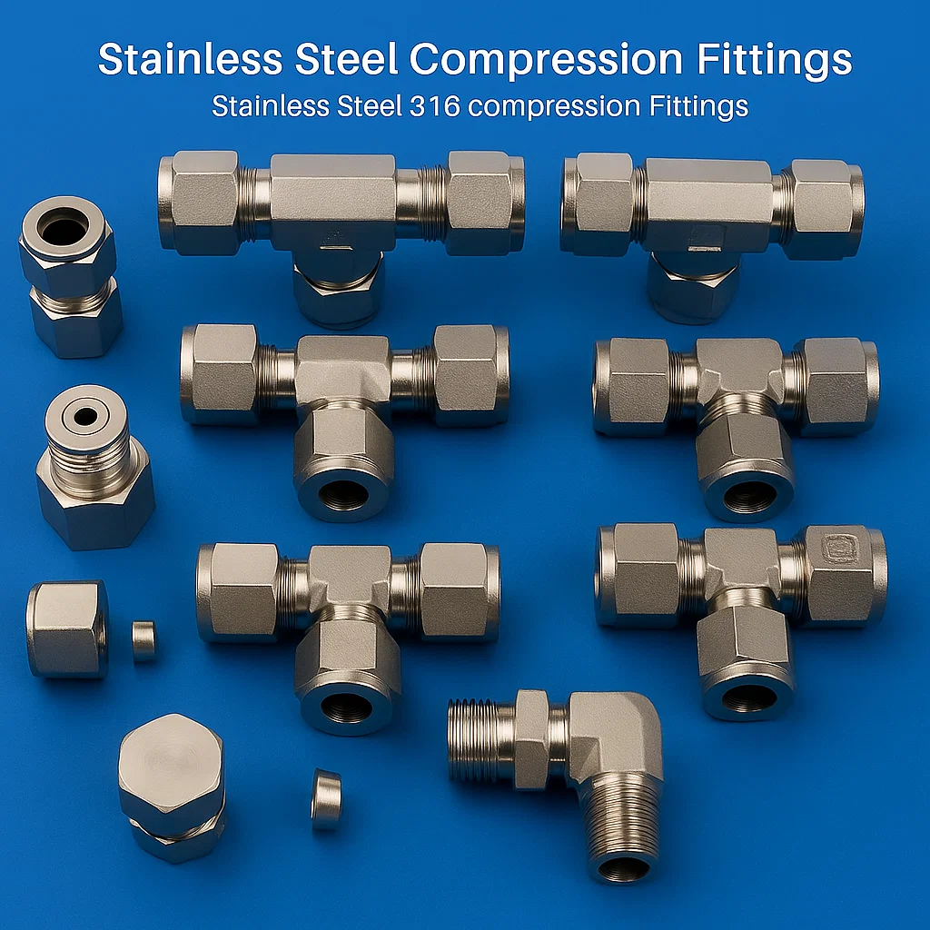
Stainless Steel Compression Fittings
Stainless steel compression fittings provide reliable, reusable, leak-tight connections for tubing systems without requiring welding, brazing, or specialized tools, making them ideal for instrumentation, process control, analytical equipment, sampling systems, and high-purity applications in pharmaceutical, semiconductor, chemical processing, and laboratory environments. The compression fitting sealing mechanism utilizes precision-manufactured ferrules (single or double ferrule designs) that undergo controlled plastic deformation when tightening the compression nut, creating metal-to-metal seal between ferrule outer surface and fitting body, plus ferrule inner surface gripping tube outer diameter. This dual sealing action provides leak-tight performance for pressures up to 20,000 PSI (1379 bar) in smaller tube sizes and 6000 PSI (414 bar) in larger sizes, with leak rates typically below 1×10⁻⁹ std cc/sec helium ensuring suitability for high-vacuum applications and ultra-high-purity gas delivery systems.
Compression Fitting Design Types
Double Ferrule Compression Fittings
Double ferrule (twin ferrule) design represents the premium compression fitting configuration featuring a front ferrule (soft nose) and back ferrule (harder material) providing superior vibration resistance, wider tube tolerance accommodation, and enhanced leak performance compared to single ferrule designs. During installation, the back ferrule drives into the tube OD creating a mechanical grip preventing tube pullout under pressure, while simultaneously driving the front ferrule into the fitting body taper creating the primary pressure seal. This sequential deformation mechanism allows remakes (disconnection and reconnection) without replacing ferrules, provided proper installation procedures are followed. Tube size compatibility ranges from 1/16″ OD (1.6mm) through 2″ OD (50.8mm) with intermediate fractional and metric sizes. Material combinations typically employ 316 stainless steel for body and nut components with 316 or 316L ferrules optimized for specific tube materials and operating conditions.
Single Ferrule Compression Fittings
Single ferrule compression fittings utilize one ferrule component featuring a combination sealing/gripping geometry that simultaneously creates tube grip and body seal in a single component. This simplified design reduces component count and cost while maintaining reliable performance for pressures up to 3000-6000 PSI depending on size. Single ferrule fittings typically require replacement of ferrule upon disconnection making them more suitable for permanent or semi-permanent installations. The ferrule features a wedge angle typically 22-24° matching the body taper angle, with precision surface finish (Ra 0.8 micrometers or better) on sealing surfaces ensuring reliable seal formation under 1/4 to 1 turn installation torque beyond finger-tight condition.
Technical Specifications and Performance Data
| Tube Size OD | Pressure Rating @ 70°F | Tube Wall Thickness | Installation Torque | Burst Pressure (4:1 Safety Factor) |
|---|---|---|---|---|
| 1/16″ (1.6mm) | 20,000 PSI (1379 bar) | 0.008″-0.020″ | 1/4 turn + 1/4 turn | 80,000 PSI |
| 1/8″ (3.2mm) | 15,000 PSI (1034 bar) | 0.020″-0.035″ | 1/4 turn + 1/4 turn | 60,000 PSI |
| 1/4″ (6.4mm) | 10,000 PSI (690 bar) | 0.028″-0.049″ | 1-1/4 turn | 40,000 PSI |
| 3/8″ (9.5mm) | 7,500 PSI (517 bar) | 0.035″-0.065″ | 1-1/4 turn | 30,000 PSI |
| 1/2″ (12.7mm) | 6,000 PSI (414 bar) | 0.049″-0.083″ | 1-1/4 turn | 24,000 PSI |
| 3/4″ (19.1mm) | 3,750 PSI (259 bar) | 0.065″-0.109″ | 1-1/2 turn | 15,000 PSI |
| 1″ (25.4mm) | 3,000 PSI (207 bar) | 0.083″-0.120″ | 1-1/2 turn | 12,000 PSI |
Compatible Tubing Standards and Materials
Compression fittings accommodate precision tubing manufactured to ASTM A269 (seamless and welded austenitic stainless steel), ASTM A213 (seamless ferritic and austenitic steel boiler, superheater, and heat-exchanger tubes), and ASTM A511 (seamless stainless steel mechanical tubing) specifications. Tube outside diameter tolerances typically ±0.005″ (±0.127mm) for imperial sizes and ±0.10mm for metric sizes ensure reliable ferrule sealing performance. Tube wall thickness selection balances internal pressure containment requirements with external compression forces during fitting installation. Soft-annealed tubing (60-80 HRB hardness) provides optimal ferrule gripping and sealing characteristics, while hard-drawn tubing may require annealing of tube ends prior to fitting installation. Compatible tube materials include 304, 304L, 316, 316L, and 316Ti stainless steels with ferrule material selection matching tube material preventing galvanic corrosion concerns.
Installation Procedures and Best Practices
Proper Installation Steps for Double Ferrule Compression Fittings:
- Cut tube squarely using tube cutter or saw (remove all burrs with deburring tool)
- Mark tube insertion depth (full insertion into fitting body bore required)
- Slip nut onto tube followed by back ferrule (chamfer facing nut) and front ferrule
- Insert tube assembly into fitting body until tube bottoms in fitting bore
- Finger-tighten nut ensuring tube remains fully inserted during tightening
- Mark nut position at finger-tight condition using permanent marker
- Apply 1-1/4 turns of wrench torque on nut while holding fitting body stationary
- For sizes 1/4″ and larger, use recommended torque values or gap inspection method
- Pressure test system and inspect for leaks before putting into service
- For remakes, apply 1/4 turn additional torque (do not exceed 1-1/2 total turns from finger-tight)
Applications and Industry Usage
- Analytical Instrumentation: Gas chromatographs, mass spectrometers, spectrophotometers requiring leak-free connections for carrier gases and samples
- Process Control Systems: Pneumatic control lines, instrument air distribution, sensing lines for pressure transmitters and flow meters
- Sampling Systems: Representative sample extraction from process streams for online analyzers and laboratory analysis
- High-Purity Gas Distribution: Semiconductor fabrication, pharmaceutical manufacturing, research laboratories requiring contamination-free gas delivery
- Hydraulic Systems: High-pressure hydraulic control circuits, accumulator connections, pressure gauge installations
- Chemical Injection Systems: Corrosion inhibitor injection, catalyst injection, chemical metering pump connections
- Vacuum Systems: Leak-tight connections for high vacuum and ultra-high vacuum applications in research and industrial processes
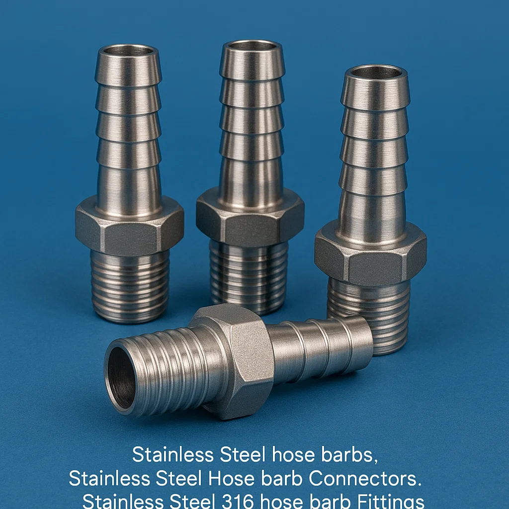
Stainless Steel Hose Barbs
Stainless steel hose barbs (also called hose nipples, hose stems, or hose adapters) provide secure connection interfaces between flexible hoses and rigid piping systems, featuring multiple barbed ridges that mechanically grip hose inner diameter preventing blowoff under pressure while the hose outer surface is typically secured with hose clamps, crimp ferrules, or push-on connections for additional retention. These components excel in applications requiring corrosion resistance, sanitary conditions, temperature extremes, or chemical compatibility where brass or plastic barb materials would be unsuitable. Manufacturing from 304, 304L, 316, and 316L stainless steel grades via precision CNC machining or cold forming processes produces barb configurations optimized for flexible hose materials including silicone rubber, EPDM, Viton®, Tygon®, polyurethane, and PVC across pressure ranges from low-pressure gravity drainage systems through pressurized applications up to 150-300 PSI depending on hose specification and clamping method employed.
Hose Barb Design Configurations
Straight Hose Barbs
Straight barb fittings feature parallel barbed section on one end with male NPT thread, female NPT thread, socket weld, butt weld, tri-clamp ferrule, or plain shank on opposite end providing inline connection between hose and threaded port, welded connection, or another hose. Barb diameters range from 1/8″ (3mm) through 4″ (100mm) with barb outside diameter typically 0.010″-0.030″ (0.25-0.75mm) larger than nominal hose ID creating interference fit. The number of barbs varies from 2-6 depending on length and pressure requirements, with barb spacing typically 0.25″-0.5″ (6-12mm) center-to-center. Critical barb geometry parameters include barb angle (typically 15-30°), radius at barb root (0.015″-0.030″ preventing hose damage), and barb height (0.020″-0.060″ providing adequate grip without excessive insertion force).
Elbow and Tee Hose Barbs
Elbow barb fittings incorporate 45°, 60°, or 90° direction changes reducing hose bending stress and space requirements in confined installations. Tee barb configurations provide branch connections for hose manifolding applications. These complex geometries are typically manufactured via investment casting or machining from bar stock depending on size and production volume. Casting allows economical production of complex multi-outlet configurations while machining provides tighter dimensional tolerances and superior surface finish for hygienic applications.
Sanitary Hose Barbs
Sanitary hose barbs designed for pharmaceutical, food processing, and biotechnology applications feature electropolished surfaces (Ra ≤0.4 micrometers), crevice-free designs, 3-A sanitary standards compliance, and tri-clamp ferrule connections enabling tool-free assembly/disassembly for cleaning validation. The barbed section maintains smooth transitions without sharp corners, with all surfaces drainable to prevent bacterial growth. Materials limited to 316L stainless steel per ASTM A270 specifications with complete material traceability and 3.1 certification provided.
Hose Retention Methods
| Retention Method | Pressure Capability | Installation | Advantages | Typical Applications |
|---|---|---|---|---|
| Worm Gear Clamps | Up to 150 PSI | Screwdriver tightening | Reusable, adjustable, field serviceable | General purpose, water, air, chemicals |
| T-Bolt Clamps | Up to 200 PSI | Wrench tightening | Higher strength, uniform clamping | Heavy-duty applications, vibration resistance |
| Spring Clamps | Up to 100 PSI | Pinch-on installation | Quick installation, constant tension | Automotive cooling systems, low pressure |
| Crimp Ferrules | Up to 300 PSI | Hydraulic crimping tool | Permanent connection, highest strength | High-pressure hose assemblies |
| Push-Lock | Up to 250 PSI | Push-on (no clamps) | Fast assembly, clean appearance | Aerospace, racing, quick-connect systems |
| Oetiker Clamps | Up to 180 PSI | Crimping tool | Tamper-proof, vibration resistant | Automotive, industrial, OEM assemblies |
Material Selection and Compatibility
Hose barb material selection must consider chemical compatibility with both process fluid and hose material, operating temperature range, and potential galvanic corrosion concerns when dissimilar metals contact in electrolyte presence. Grade 304 stainless steel provides economical solution for general purpose applications including water, air, and mild chemicals at temperatures from -40°F to +400°F (-40°C to +204°C). Grade 316/316L offers superior corrosion resistance for marine environments, chloride exposure, sulfuric acid (dilute concentrations), and pharmaceutical applications. Grade 316Ti provides enhanced high-temperature strength and prevents sensitization in applications involving welding or sustained temperatures in the 800-1500°F (427-816°C) range.
Compatible Hose Materials
- Silicone Rubber: -60°C to +200°C, food grade, pharmaceutical
- EPDM: -40°C to +150°C, weather resistant, water/steam service
- Viton® (FKM): -20°C to +200°C, excellent chemical resistance
- NBR (Nitrile): -40°C to +100°C, oil and fuel resistant
- Polyurethane: -40°C to +80°C, abrasion resistant, air tools
- PVC: -10°C to +60°C, economical, water and air service
- PTFE (Teflon®): -200°C to +260°C, universal chemical resistance
Size Selection Criteria
- Barb OD should be 5-10% larger than hose ID
- Minimum hose wall thickness: 1/16″ (1.5mm)
- Hose ID tolerance: ±3-5% typical
- Insertion depth: Minimum 1.5× hose ID
- Straight length before bend: Minimum 2× hose ID
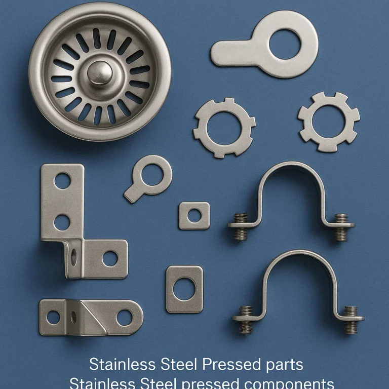
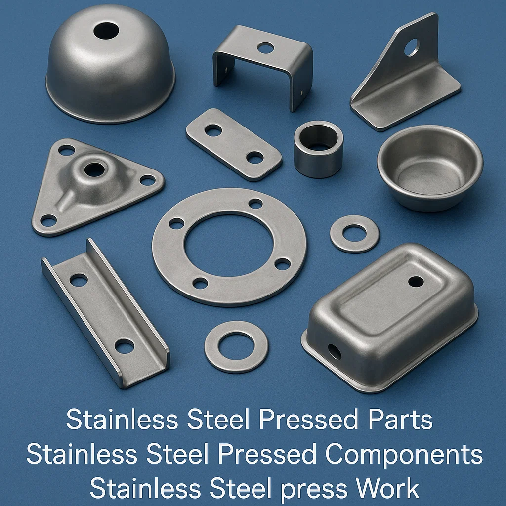
Stainless Steel Pressed Parts & Pressed Components
Stainless steel pressed parts (also termed stamped parts when using progressive dies or stampings when produced via blanking operations) represent cost-effective manufacturing solutions for high-volume production of flat or formed sheet metal components leveraging mechanical or hydraulic press equipment ranging from 20-ton benchtop presses through 1000-ton+ tandem press lines to shape stainless steel sheet, strip, or coil materials into finished or semi-finished components through operations including blanking, piercing, bending, drawing, embossing, coining, and trimming. Our comprehensive pressing capabilities accommodate material thicknesses from 0.1mm (0.004″) ultra-thin foil through 6mm (0.236″) heavy plate with press bed sizes from 300mm × 300mm through 2000mm × 3000mm enabling component dimensions from miniature electronic contacts and spring clips through large appliance panels and automotive body components. Material grades processed include austenitic (304, 304L, 316, 316L, 321), ferritic (409, 430, 439), martensitic (410, 420), duplex (2205), and precipitation hardening (17-4PH, 17-7PH) stainless steels in various temper conditions from full-hard through soft-annealed depending on forming severity requirements.
Press Forming Processes and Capabilities
Blanking and Piercing Operations
Blanking operations cut external contours separating finished parts or intermediate blanks from sheet material while piercing creates internal holes, slots, or cutouts within part boundaries. Die clearance between punch and die critical to edge quality typically ranges from 5-10% of material thickness for stainless steels, with tighter clearances (3-5%) producing sheared edges with larger burnished zone and smaller fracture zone, while larger clearances (10-15%) reduce punch/die wear at expense of increased burr height and edge rollover. Press tonnage requirements calculated using shear strength (approximately 80% of tensile strength), material thickness, and total shear length with safety factor 1.3-1.5× theoretical tonnage accommodating material hardness variations and die friction. Blanking die designs incorporate pilot pins for strip registration, spring strippers for material ejection, and scrap shedding features for continuous operation in progressive die applications.
Bending and Forming Operations
Bending operations create angular features through plastic deformation over a defined radius, with minimum bend radius related to material thickness, grain direction, and tensile properties. Austenitic stainless steels typically accommodate bend radii as tight as 1T (one times material thickness) for 90° bends with bending axis perpendicular to rolling direction, while parallel-to-rolling direction requires 1.5T minimum radius preventing cracking. Ferritic grades require larger bend radii (2-3T) due to lower ductility while precipitation hardening grades must be bent in solution-annealed condition then age-hardened post-forming. Springback compensation (overbending 2-10° depending on material properties) incorporated into tooling design ensures finished parts meet dimensional specifications. Complex 3D forming operations utilize compound dies, transfer dies, or progressive dies with multiple forming stations sequentially shaping material into finished configurations.
Deep Drawing Operations
Deep drawing forms cup-shaped or box-shaped components from flat blanks through compressive and tensile stresses as material flows over draw die radius into cavity. Drawing ratio (DR = blank diameter ÷ punch diameter) limitations vary by material with austenitic stainless steels achieving DR up to 2.2:1 in single operations, while multiple draws with intermediate annealing enable complex shapes with depth-to-diameter ratios exceeding 3:1. Critical parameters include blank holder force preventing wrinkling during draw, die radii balancing material flow and thinning (typically 4-8T for stainless steels), punch-die clearance (1.05-1.15× material thickness), and lubrication selection (chlorinated oils, synthetic drawing compounds, dry film lubricants).
Progressive Die Stamping
Progressive die stamping integrates multiple operations (piercing, notching, forming, bending, drawing) within a single die set featuring multiple stations through which material strip advances incrementally with each press stroke. This high-volume production method achieves cycle rates from 30-200 strokes per minute depending on part complexity, press capabilities, and material feed system sophistication. Progressive dies accommodate strip widths from 25mm through 600mm with strip thickness typically 0.3mm to 3mm for most applications. Die design considerations include station sequence optimization, scrap web design maintaining adequate strip strength throughout progression, pilot pin placement ensuring accurate registration between stations, and end-of-strip detection preventing die damage from material runout. Lead time for progressive die development ranges from 8-16 weeks with tooling costs amortized over production quantities typically exceeding 50,000 pieces annually.
Material Specifications for Pressing Applications
| Material Grade | Temper/Hardness | Formability Rating | Typical Applications | Special Considerations |
|---|---|---|---|---|
| 304/304L | Annealed (70-85 HRB) | Excellent (Drawing quality) | Sinks, cookware, appliances, architectural panels | Best overall formability, standard grade |
| 316/316L | Annealed (70-90 HRB) | Excellent (Deep drawing) | Marine hardware, medical devices, food equipment | Molybdenum enhances corrosion resistance |
| 430 | Annealed (70-85 HRB) | Good (Moderate forming) | Automotive trim, appliance panels, decorative | Magnetic, lower cost, limited deep drawing |
| 410 | Annealed (85-95 HRB) | Fair (Limited forming) | Turbine blades, valve components, springs | Form before heat treating, becomes brittle when hardened |
| 17-7PH | Condition A (26-32 HRC) | Good in annealed (Excellent spring characteristics) | Springs, clips, fasteners, aerospace components | Form in Condition A, age harden to Condition C (RH950) |
| 301 | 1/4 Hard to Full Hard | Limited (Pre-tempered for springs) | Spring washers, spring clips, electrical contacts | Higher work-hardening rate than 304, excellent spring properties |
Surface Finishes and Post-Processing
Pressed stainless steel components utilize various mill finishes including 2B (bright annealed and cold rolled), 2D (dull finish), BA (bright annealed mirror finish), and 2E (matte finish) providing surface roughness ranging from Ra 0.05 micrometers (BA) through 0.8 micrometers (2D). Post-pressing operations include deburring via vibratory finishing or barrel tumbling (removing sharp edges), stress relief annealing (reducing forming stresses), passivation per ASTM A380/A967 (enhancing corrosion resistance), electropolishing (decorative finish and improved cleanability), powder coating or e-coating (additional corrosion protection), and assembly operations including spot welding, projection welding, hardware insertion, and quality inspection. Secondary machining operations (tapping, reaming, counterboring) performed on pressed components utilizing CNC machining centers or dedicated drilling/tapping machines as required by design specifications.
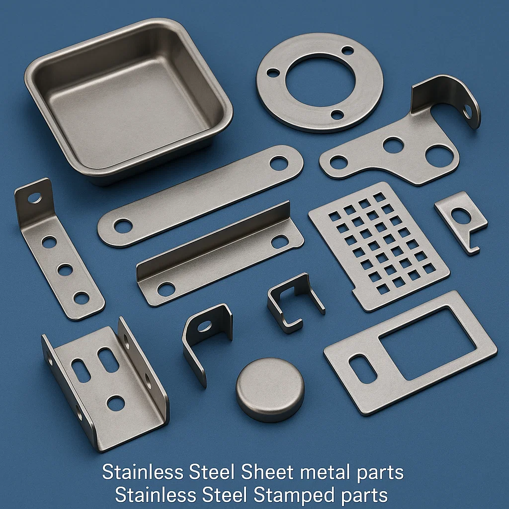
Stainless Steel Stamping & Stamped Parts and Components
Stainless steel stamping represents a specialized subset of metal forming encompassing progressive die stamping, compound die stamping, transfer stamping, and fine blanking operations producing precision components with tighter tolerances (±0.05mm to ±0.15mm), superior edge quality, and complex geometrical features compared to conventional pressing operations. High-speed stamping presses operating at 200-800 strokes per minute with servo drive technology enabling programmable motion profiles optimize material flow, reduce secondary operations, and achieve economical per-piece costs for production volumes ranging from 100,000 to 10,000,000+ pieces annually. Our stamping expertise encompasses automotive components (brackets, clips, mounting hardware, structural reinforcements), electronic enclosures (shielding cans, connector housings, heat sinks, spring contacts), appliance components (drum assemblies, door panels, structural supports), medical device parts (surgical instrument components, implantable device housings), and aerospace precision parts (brackets, clips, electrical contacts) manufactured from stainless steel strip thicknesses 0.05mm (0.002″) through 4mm (0.157″) in widths up to 600mm.
Advanced Stamping Technologies
Fine Blanking
Fine blanking (also termed precision blanking) produces parts with 100% smooth sheared edges eliminating secondary machining operations through triple-action press mechanism applying blanking force, V-ring impingement force (preventing material movement), and counter-force (supporting material during shearing). This process achieves flatness tolerances within 0.05mm across 100mm span, edge perpendicularity within ±1° from nominal, and edge surface roughness Ra <1.6 micrometers. Fine blanking particularly benefits components requiring tight hole-to-edge distance (as close as 0.5T vs. 1.5-2T for conventional stamping), close feature spacing, and precise gear teeth or spline profiles. Press tonnages typically 2-3× conventional blanking due to simultaneous application of blanking and impingement forces with cycle rates limited to 30-100 strokes/minute compared to 200+ strokes/minute for high-speed progressive dies.
Transfer Stamping
Transfer stamping systems utilize mechanical or magnetic transfer mechanisms moving partially formed parts between die stations, accommodating larger part sizes and more complex forming sequences than progressive dies where parts remain attached to strip. Transfer systems enable bidirectional part movement, part rotation between stations, and multi-path processing for complex assemblies. Typical applications include large automotive structural components, appliance drum assemblies, and complex brackets requiring operations exceeding single press bed capacity. Transfer press lines integrate 3-8 press stations with part transfer systems achieving cycle rates of 15-40 parts per minute depending on part complexity and transfer distance.
Servo Press Stamping
Servo-driven stamping presses replace conventional flywheel/clutch/brake mechanisms with AC servo motors providing programmable slide motion including variable speed during forming stroke, dwell time at bottom dead center for coining/ironing operations, and optimized acceleration/deceleration profiles reducing shock loads and extending die life. Servo press technology enables forming operations previously requiring multiple presses (draw, restrike, trim) within single press through programmable motion control. Energy consumption reduced 30-60% compared to mechanical presses while press tonnage available throughout stroke rather than only near bottom dead center. Slide position accuracy within ±0.01mm ensures consistent part quality throughout production runs.
Tooling Design and Maintenance
Stamping die construction utilizes tool steels including D2 (HRC 58-62) for cutting sections requiring high wear resistance, A2 (HRC 58-62) for structural components requiring toughness, S7 (HRC 54-58) for shock-resistant applications, and carbide inserts (HRC 72-82) for ultra-high-volume production or difficult-to-stamp materials. Die sets incorporate precision guide systems (ball bearing guides, ball cages) maintaining alignment tolerances within ±0.005mm preventing punch/die misalignment causing premature wear or breakage. Maintenance intervals established through tool monitoring systems tracking punch force, slide position, and vibration signatures enabling predictive maintenance scheduling before catastrophic failures occur. Typical die life ranges from 500,000 to 5,000,000 hits depending on material hardness, part complexity, and maintenance quality with punch/die sharpening performed at 50,000-200,000 hit intervals restoring cutting edges to original geometry.
Stamping Process Selection Guide:
- Progressive Die: High volume (100k-10M+ pieces), simple to moderate complexity, part size <300mm, thickness 0.3-3mm
- Transfer Stamping: Medium to high volume (50k-1M pieces), complex geometry, large parts >300mm, multiple forming operations
- Fine Blanking: Medium volume (10k-500k pieces), precision requirements, smooth sheared edges, close tolerances ±0.05mm
- Compound Die: Medium volume (25k-500k pieces), flat parts, piercing and blanking in one stroke, high accuracy
- Four-Slide Stamping: Wire forming and complex bending, spring clips, intricate bent configurations
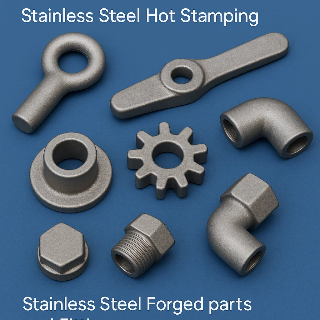
Stainless Steel Forging
Stainless steel forging encompasses hot forging, warm forging, and cold forging processes that plastically deform solid metal through compressive forces applied via hammers, presses, or upset machines, producing components with superior mechanical properties, grain flow aligned with part geometry, and higher strength-to-weight ratios compared to cast or machined equivalents. Our forging capabilities span open-die forging for large custom shapes and prototypes, closed-die (impression die) forging for medium to high-volume precision components, and upset forging for fasteners and shaft-end features. Press capacities range from 300-ton mechanical presses for small precision forgings through 3000-ton hydraulic presses handling workpieces up to 500kg with forging temperatures optimized by grade: austenitic stainless steels 1050-1200°C, martensitic grades 950-1150°C, and precipitation hardening grades 1050-1175°C. Typical forged products include valve bodies, flanges, fittings, structural components, aerospace brackets, landing gear components, pump shafts, turbine disks, and high-strength fasteners manufactured from bar stock, billet, or ingot materials per ASTM A182, A336, A473, and AMS specifications.
Forging Process Technologies
Hot Forging (Precision Die Forging)
Hot forging operations heat workpieces to temperatures above recrystallization temperature (typically 950-1200°C for stainless steels) enabling significant plastic deformation with minimal work hardening, accommodating complex geometries, and achieving near-net-shape accuracy minimizing machining requirements. Induction heating systems provide rapid, uniform heating with temperature control within ±10°C critical for consistent flow characteristics and microstructure development. Multi-station forging sequences progressively shape preforms through blocker dies (initial distribution of material), finisher dies (final geometry), and trimming operations (removing flash). Die design incorporates draft angles (3-7°) enabling part extraction, flash land geometry controlling material flow, and die polish (Ra 0.8-1.6 micrometers) providing superior surface finish. Forging tolerances achievable within ±0.5mm to ±2mm depending on part dimensions with linear shrinkage of 1.5-2.5% accommodated in die cavity design.
Isothermal and Hot-Die Forging
Isothermal forging maintains dies at elevated temperatures (typically 800-1000°C for stainless steels) approximating workpiece temperature, eliminating thermal gradients that cause non-uniform deformation, reducing forging loads by 30-50%, and enabling complex shapes with minimal draft angles (<1°) approaching net-shape manufacturing. This process particularly benefits aerospace components (turbine disks, compressor blades, structural forgings) and medical implants requiring complex geometries from difficult-to-forge materials including superalloys and titanium alloys. Press speeds dramatically reduced (0.1-10 mm/second vs. 100-500 mm/second for conventional forging) enabling superplastic forming conditions and near-isothermal deformation throughout workpiece volume. Capital equipment costs significantly higher due to hot-die tooling, controlled atmosphere requirements, and specialized heating systems limiting applications to high-value components justifying premium processing costs.
Cold Forging and Precision Forming
Cold forging operations performed at room temperature or slightly elevated temperatures (below recrystallization temperature) produce precision components with excellent surface finish (Ra 0.4-1.6 micrometers as-forged), tight dimensional tolerances (±0.05mm to ±0.15mm), substantial work hardening increasing strength 20-50% over annealed condition, and elimination of scaling/decarburization associated with hot forging. Austenitic stainless steels’ high work-hardening rate limits cold forging to relatively simple geometries (upset heads on fasteners, shallow drawn cups, simple extrusions) with area reductions typically <60% in single operations. Intermediate annealing may be required for complex cold-formed parts involving multiple forming stages. Lubrication critical to cold forging success with phosphate coatings plus soap lubricants or polymer-bonded films preventing galling and extending die life. Cold forging particularly economical for high-volume fastener production, precision hardware components, and automotive electrical contacts where superior surface finish eliminates secondary finishing operations.
Forging Material Properties and Specifications
| Material Grade | Forging Temp Range | Typical Applications | Mechanical Properties (Forged + Heat Treated) |
|---|---|---|---|
| 304/304L | 1050-1175°C | Flanges, valve bodies, structural components | Tensile: 515-620 MPa, Yield: 205-275 MPa, Elongation: 40% |
| 316/316L | 1050-1200°C | Marine components, chemical processing equipment, shafts | Tensile: 515-620 MPa, Yield: 205-310 MPa, Elongation: 40% |
| 321 | 1050-1175°C | High-temperature flanges, exhaust components | Tensile: 515-655 MPa, Yield: 205-275 MPa, Elevated temp strength |
| 410 | 950-1150°C | Pump shafts, turbine components, high-strength fasteners | Tensile: 655-965 MPa, Yield: 415-760 MPa (heat treated), 40 HRC |
| 17-4PH | 1050-1150°C | Aerospace brackets, landing gear, high-performance components | Tensile: 1310-1380 MPa, Yield: 1170-1240 MPa (H1150), 35-40 HRC |
| Duplex 2205 | 1020-1100°C | Offshore components, high-strength marine hardware | Tensile: 655-890 MPa, Yield: 450-620 MPa, Excellent SCC resistance |
Post-Forging Operations and Quality Control
Forged components undergo comprehensive heat treatment including solution annealing for austenitic grades (1040-1150°C rapid cool), annealing and tempering for martensitic grades (870-1010°C quench then 540-650°C temper), or solution annealing and aging for precipitation hardening grades (1040-1050°C rapid cool then 480-620°C age). Descaling operations remove oxidation scale via shot blasting, acid pickling, or wire brushing depending on surface finish requirements. Machining operations produce finished dimensions, sealing surfaces, threaded connections, and precision features with forging serving as near-net-shape preform reducing material waste and machining time by 40-70% compared to bar stock machining. Quality verification includes dimensional inspection per forging drawings, ultrasonic inspection per ASTM A388 for internal soundness, magnetic particle or liquid penetrant testing for surface defects, hardness verification, and tensile testing for mechanical property conformance.
Stainless Steel Turned Parts & Screw Machine Parts
Stainless steel turned parts and screw machine parts represent precision cylindrical components manufactured via CNC turning operations on conventional engine lathes, CNC lathes, multi-spindle automatic lathes, or Swiss-type automatic screw machines, producing shafts, pins, bushings, sleeves, spacers, fasteners, precision instrument components, and complex rotational geometries with diameter tolerances within ±0.005mm to ±0.025mm and surface finishes from Ra 0.1 to 3.2 micrometers. Swiss screw machining particularly excels for small diameter precision parts (0.5mm to 32mm diameter) requiring length-to-diameter ratios exceeding 10:1, featuring guide bushing support minimizing workpiece deflection during machining operations while rotating cutting tools perform turning, drilling, milling, threading, and cross-drilling operations producing complex features in single machine setup. Production capabilities span prototype single pieces through high-volume runs exceeding 1,000,000 pieces annually with cycle times ranging from 15 seconds for simple bushings through 300 seconds for complex multi-featured components incorporating secondary operations within the machine cycle.
CNC Turning Operations and Capabilities
Conventional CNC Lathe Turning
CNC engine lathes with chuck capacities from 150mm to 500mm and between-centers distances up to 2000mm accommodate workpieces from small precision parts through large diameter shafts and sleeves. Operations include OD turning (roughing and finishing), facing (end surface machining), grooving (O-ring grooves, retaining ring grooves, undercuts), threading (60° V-threads, ACME, buttress, multi-start), ID turning (boring operations), drilling (center drilling, through-holes, deep holes), and parting (cutoff operations). Modern CNC lathes feature live tooling capabilities integrating powered rotating tools enabling off-axis milling, drilling, and tapping operations typically requiring secondary milling operations. Bar feeders supply bar stock material (12mm to 80mm diameter) continuously enabling lights-out manufacturing for production quantities, while workpieces exceeding bar feeder capacity utilize manual chuck loading or robotic part handling systems.
Swiss-Type CNC Screw Machining
Swiss-type screw machines revolutionize small diameter precision component production through unique guide bushing design supporting workpiece immediately adjacent to cutting zone (typically 1-3mm from tool), minimizing deflection and enabling extreme length-to-diameter ratios unattainable on conventional lathes. The guide bushing remains stationary while material advances through rotating bushing as machining progresses along Z-axis. Multiple tool stations (6-12 positions on main spindle, 4-6 positions on sub-spindle) perform simultaneous operations dramatically reducing cycle time. Sub-spindle pickup capability transfers parted workpieces for backside operations (drilling, threading, chamfering) completing parts without manual intervention. Modern Swiss machines integrate Y-axis capability enabling off-centerline operations, B-axis tool positioning for angular features, and synchronized C-axis spindle positioning enabling complex milling operations. Material utilization optimization through part-to-part cutoff (minimal facing length between parts) reduces scrap compared to conventional turning by 20-40%.
Screw Machine Material Selection
| Grade | Machinability Rating | Typical Spindle Speed | Key Characteristics | Applications |
|---|---|---|---|---|
| 303 | 100% (Excellent) | 180-250 m/min | Free-machining with sulfur, excellent chip breaking | Fasteners, shafts, instrument components |
| 303Se | 110% (Excellent) | 200-280 m/min | Selenium addition, superior surface finish | Precision turned parts, medical instruments |
| 304 | 45% (Poor) | 80-120 m/min | Work-hardening, stringy chips, gummy | Corrosion-critical applications |
| 316 | 40% (Poor) | 70-100 m/min | More difficult than 304, requires sharp tools | Marine hardware, medical implants |
| 416 | 85% (Good) | 150-220 m/min | Martensitic free-machining grade | Valve components, pump shafts (hardened) |
| 430F | 90% (Good) | 160-240 m/min | Ferritic free-machining, magnetic | Automotive trim, decorative parts |
*Machinability rating relative to 303 stainless steel = 100%
Precision Turning Applications and Specifications
Medical Device Components
- Surgical instrument pins, shafts, and connectors
- Orthopedic bone screws and fixation devices
- Dental implant abutments and components
- Precision: ±0.005mm (±0.0002″)
- Surface finish: Ra 0.1-0.4 micrometers
- Material: 316L, 17-4PH per ASTM F138, F899
Aerospace Precision Parts
- Landing gear pins and bushings
- Actuator shafts and components
- Hydraulic system fittings and adapters
- Precision: ±0.010mm (±0.0004″)
- Certifications: AS9100, Nadcap accredited
- Material: 15-5PH, 17-4PH per AMS specifications
Instrumentation Components
- Pressure sensor housings and fittings
- Flow meter bodies and internals
- Valve stems and precision inserts
- Precision: ±0.013mm (±0.0005″)
- Thread quality: 6g/6H class
- Material: 303, 316, 316L per ASTM A582
Automotive Components
- Fuel injection components and nozzles
- Sensor housings and brackets
- Exhaust system fasteners and hardware
- Precision: ±0.025mm (±0.001″)
- Standards: IATF 16949, PPAP
- Material: 303, 430F, 410 per ASTM A582
Threading Operations and Specifications
Precision thread turning produces internal and external threads meeting ASME B1.1 (Unified inch screw threads), ASME B1.20.1 (pipe threads NPT), ISO 68-1 (metric threads), and ISO 7-1 (pipe threads BSP) specifications with thread quality classes from 6g (external) and 6H (internal) for general commercial applications through 4g6g/4H5H for precision instrumentation. Thread forms include 60° V-threads (most common), ACME 29° trapezoidal threads (power transmission), buttress threads (high axial load, one direction), multi-start threads (high lead for rapid advancement), and custom thread forms per drawing specifications. Thread rolling (cold forming) provides superior fatigue strength compared to cut threads for high-volume fastener production while thread milling accommodates interrupted threads, large pitch diameters, and difficult-to-machine materials. Thread quality verification employs thread ring/plug gauges, optical comparators, and thread micrometers ensuring pitch diameter, major diameter, minor diameter, and pitch accuracy conformance.
CNC Machining of 316 Stainless Steel Parts
CNC machining of 316 stainless steel presents unique challenges and opportunities requiring specialized knowledge of material characteristics, optimized cutting parameters, appropriate tooling selection, and rigorous process control to overcome work-hardening tendencies, poor thermal conductivity (16.3 W/m·K at 100°C vs. 50 W/m·K for carbon steel), and built-up edge formation while achieving required dimensional accuracy, surface finish, and production efficiency. Grade 316 stainless steel’s austenitic microstructure exhibits substantial work hardening during cutting operations where yield strength increases from 205 MPa (annealed) to over 800 MPa in the deformed surface layer within micrometers of the machined surface, necessitating continuous chip formation, adequate chip loads preventing rubbing, and avoidance of tool dwell preventing excessive work hardening. Successful machining strategies leverage sharp cutting edges (hone radius <0.020mm), positive rake angles (8-15°), optimized cutting speeds (70-120 m/min turning, 80-150 m/min milling), adequate feed rates maintaining chip load (0.15-0.35 mm/rev turning, 0.08-0.2 mm/tooth milling), high-pressure coolant delivery (70-150 bar), and specialized tool coatings (TiAlN, AlTiN) providing hot hardness and chemical stability.
Tool Selection and Optimization for 316 Stainless Steel
Cutting Tool Materials and Coatings
| Tool Material | Composition/Features | Applications | Recommended Coating | Tool Life vs. Uncoated |
|---|---|---|---|---|
| Carbide (ISO P25-P35) | WC + 6-12% Co binder, submicron grain | General purpose turning, milling | TiAlN, AlTiN multilayer | 2-3× improvement |
| Cermet | TiC/TiN + Ni binder, crater resistant | Finishing operations, high speed | TiN or uncoated | 1.5-2× vs. carbide |
| CBN (Cubic Boron Nitride) | PcBN low content (30-60%), high content (90%+) | Hardened martensitic SS (>45 HRC) | None (solid CBN) | 10-50× vs. carbide |
| Ceramic (Al₂O₃+TiC) | Aluminum oxide + titanium carbide | High-speed finishing (limited use for SS) | None | Variable (thermal cracking concerns) |
| HSS (High-Speed Steel) | M2, M42 grades with TiN coating | Threading, form tools, drills <10mm | TiN, TiAlN | 2-3× improvement |
Tool Geometry Optimization
Cutting tool geometry critically influences machining performance with recommendations for 316 stainless steel including positive rake angles (12-15° for roughing, 6-10° for finishing) reducing cutting forces and heat generation, large relief angles (8-12°) preventing rubbing and work hardening, sharp cutting edges with minimal honing (0.010-0.020mm radius) facilitating chip formation, and robust tool geometry preventing chipping under interrupted cutting conditions. Chipbreaker geometries designed for stainless steel feature controlled chip curl radii producing manageable chip lengths (typically C-shaped or 9-shaped chips) preventing stringy continuous chips that wrap around tools and workpieces. Insert nose radius selection balances surface finish requirements (larger radii produce finer finish) against cutting forces and chatter tendency (smaller radii reduce forces but may produce rougher surface finish). Typical nose radii range from 0.4mm for roughing operations through 1.2-1.6mm for finishing operations requiring Ra <1.6 micrometers surface finish.
Machining Parameters and Strategies
Turning Operations for 316 Stainless Steel
Roughing Parameters
- Cutting Speed (Vc): 70-100 m/min (230-330 SFM)
- Feed Rate (f): 0.2-0.35 mm/rev (0.008-0.014 ipr)
- Depth of Cut (ap): 2-5mm (0.080-0.200″)
- Tool Life: 15-25 minutes per edge
- Metal Removal Rate: 80-150 cm³/min
Finishing Parameters
- Cutting Speed (Vc): 100-150 m/min (330-500 SFM)
- Feed Rate (f): 0.08-0.15 mm/rev (0.003-0.006 ipr)
- Depth of Cut (ap): 0.3-1.0mm (0.012-0.040″)
- Surface Finish: Ra 0.8-1.6 micrometers achievable
- Tool Life: 25-40 minutes per edge
Milling Operations for 316 Stainless Steel
Face/Shoulder Milling – Roughing
- Cutting Speed (Vc): 70-110 m/min (230-360 SFM)
- Feed per Tooth (fz): 0.1-0.2 mm/tooth
- Axial Depth (ap): 3-6mm (0.120-0.240″)
- Radial Depth (ae): 50-75% cutter diameter
- Tool Life: 20-35 minutes between insert changes
Face/Shoulder Milling – Finishing
- Cutting Speed (Vc): 110-160 m/min (360-525 SFM)
- Feed per Tooth (fz): 0.05-0.12 mm/tooth
- Axial Depth (ap): 0.5-2mm (0.020-0.080″)
- Surface Finish: Ra 0.8-3.2 micrometers achievable
- Wiper Insert Usage: Improves finish 30-50%
Slot/Cavity Milling
- Cutting Speed (Vc): 60-90 m/min (200-300 SFM)
- Feed per Tooth (fz): 0.05-0.15 mm/tooth
- Strategy: Trochoidal milling for deep slots
- Coolant: High-pressure through-spindle essential
- Radial Engagement: 10-40% cutter diameter (dynamic milling)
Hole-Making (Drilling, Reaming)
- Drilling Speed: 30-60 m/min (100-200 SFM)
- Feed Rate Drilling: 0.08-0.20 mm/rev
- Reaming Speed: 20-40 m/min (65-130 SFM)
- Peck Drilling: Required for holes >3× diameter deep
- Through-Coolant Drills: Mandatory for holes >5× diameter
Common Machining Challenges and Solutions
| Challenge | Cause | Solution | Expected Result |
|---|---|---|---|
| Excessive Work Hardening | Low cutting speed, dull tools, insufficient feed rate | Maintain adequate chip load (>0.15mm/rev), use sharp tools, avoid dwelling | Consistent tool life, improved surface finish |
| Built-Up Edge (BUE) | Incorrect speed/feed combination, inadequate cooling | Increase cutting speed to 80+ m/min, high-pressure coolant, coated tools | Elimination of BUE, better surface finish |
| Poor Surface Finish | Work hardening, BUE formation, vibration, worn tools | Sharp tools with wiper geometry, stable setup, proper speeds/feeds | Ra <1.6 micrometers achievable consistently |
| Rapid Tool Wear | Excessive cutting speed, poor tool coating, interrupted cuts | Reduce speed 10-20%, use AlTiN coated carbide, adjust tool path | 2-3× tool life improvement |
| Stringy Chips | High ductility, inadequate chipbreaker, low feed rates | Use positive chipbreaker geometry, increase feed rate, peck cycles | Manageable chip lengths <100mm |
| Chatter/Vibration | Insufficient rigidity, overhang, resonance frequencies | Reduce overhang, use damped tool holders, adjust RPM ±10% | Stable cutting, improved finish and accuracy |
Quality Control and Surface Integrity
Machined 316 stainless steel components require comprehensive quality verification including dimensional inspection via CMM systems (±0.002mm accuracy), surface finish measurement using contact or optical profilometers verifying Ra, Rz, and waviness parameters, surface integrity assessment evaluating residual stress states (compressive preferred, tensile detrimental), microhardness profiling detecting work-hardened zones (typical subsurface hardness 150-250 HV vs. 140-160 HV bulk), and metallurgical examination confirming absence of thermally affected zones, phase transformations, or microstructural damage. Proper machining practices produce components with compressive residual stresses (beneficial for fatigue performance), minimal work-hardened layer depth (<50 micrometers), and surface finish appropriate for application requirements ranging from Ra 3.2 micrometers for structural components through Ra 0.4 micrometers for sanitary or sealing surfaces.
Get Your Premium Stainless Steel Parts Today
Contact our technical experts for detailed quotations, engineering support, and customized manufacturing solutions for your specific requirements.
Manufacturing Capabilities
- CNC Machining (3, 4, 5-axis)
- Investment & Sand Casting
- Hot & Cold Forging
- Progressive Die Stamping
- Swiss Screw Machining
- Heat Treatment & Finishing
Quality Certifications
- ISO 9001:2015
- ISO 14001:2015
- OHSAS 18001
- AS9100 (Aerospace)
- ISO 13485 (Medical)
- IATF 16949 (Automotive)
Material Grades Available
- 304, 304L, 316, 316L, 316Ti
- 303, 321, 317L
- 410, 420, 430, 440C
- 17-4PH, 15-5PH, 17-7PH
- Duplex 2205, 2507
- Custom alloys available
Why Choose Us?
Delivery Time: 4-6 Weeks | Global Shipping Available | ISO Certified Quality | Custom Manufacturing Welcome
Industries We Serve
🏭 Chemical Processing
Corrosion-resistant fittings, valve bodies, pump components, and process equipment for handling acids, bases, and aggressive chemicals
💊 Pharmaceutical
Sanitary fittings, sterile process equipment, cleanroom components, and medical device parts meeting FDA 21 CFR and 3-A standards
🍽️ Food & Beverage
Food-grade fittings, sanitary tri-clamp components, brewing equipment, and dairy processing parts with electropolished finishes
⚓ Marine & Offshore
Seawater-resistant 316 components, offshore platform hardware, marine vessel fittings, and subsea equipment parts
🛢️ Oil & Gas
High-pressure fittings, valve components, wellhead equipment, and sour gas service parts for upstream/downstream operations
⚡ Power Generation
Turbine components, boiler parts, heat exchanger components, and cooling system fittings for conventional and renewable energy
✈️ Aerospace
Precision machined brackets, hydraulic fittings, landing gear components, and structural parts meeting AS9100 standards
🚗 Automotive
Exhaust system components, fuel system parts, sensor housings, and decorative trim meeting IATF 16949 requirements
🏥 Medical Devices
Surgical instruments, implantable device components, diagnostic equipment parts, and laboratory hardware per ISO 13485
💧 Water Treatment
Desalination equipment, water purification fittings, pump components, and distribution system parts
🏗️ Architecture
Structural components, handrail fittings, decorative hardware, and building facade elements with various surface finishes
🔬 Semiconductor
Ultra-high-purity gas delivery fittings, vacuum chamber components, and cleanroom-compatible precision parts
Technical Resources & Support
Documentation Available
- Material Test Certificates (MTC): Complete chemical composition and mechanical properties per EN 10204 Type 3.1
- Dimensional Inspection Reports: First article inspection reports (FAIR) per AS9102 with full CMM data
- Pressure Test Certificates: Hydrostatic test records with witnessed test data and certifications
- Heat Treatment Records: Temperature charts, soak times, cooling rates, and hardness verification
- NDT Reports: Radiographic, ultrasonic, penetrant testing results with inspector certifications
- Certificates of Compliance: DFARS, RoHS, REACH, Conflict Minerals declarations
- Traceability Documentation: Complete material traceability from mill through final shipment
- 3D CAD Models: STEP, IGES, Parasolid formats for design integration
- 2D Engineering Drawings: PDF and DWG formats with GD&T callouts per ASME Y14.5
Engineering Support Services
- Design for Manufacturability (DFM): Review and optimization of designs to improve manufacturability and reduce costs
- Material Selection Assistance: Expert guidance selecting optimal stainless steel grades for specific applications
- Finite Element Analysis (FEA): Structural analysis, stress calculation, and performance simulation
- Process Optimization: Recommendation of most cost-effective manufacturing methods for your requirements
- Prototyping Services: Rapid prototyping from single pieces through pre-production quantities
- Reverse Engineering: Dimensional inspection and CAD model generation from existing parts
- Quality Planning: APQP, PPAP, Control Plans, and FMEA development for critical applications
- On-Site Technical Support: Field service and installation assistance for complex assemblies
Frequently Asked Questions (FAQ)
General Questions
Q1: What is the difference between 304 and 316 stainless steel?
A: The primary difference is that 316 stainless steel contains 2-3% molybdenum, which 304 does not have. This molybdenum addition provides 316 with superior resistance to pitting corrosion, crevice corrosion, and chloride-induced stress corrosion cracking, making it the preferred choice for marine environments, chemical processing, and medical applications. Grade 304 is more economical and suitable for general purpose applications not involving chlorides or harsh chemicals.
Q2: What are your minimum order quantities?
A: Minimum order quantities vary by manufacturing process. For custom CNC machined parts, we accept orders starting from 1 piece for prototypes. Investment castings typically require 100+ pieces minimum. Progressive die stampings are economical starting from 10,000 pieces. Forged components typically have 500-1000 piece minimums. Contact us for specific MOQ information based on your part requirements.
Q3: What tolerances can you achieve?
A: CNC machined components: ±0.005mm to ±0.025mm general tolerances, ±0.002mm for critical features. Investment castings: CT7-CT9 per ISO 8062. Sand castings: CT10-CT13. Forged parts: ±0.5mm to ±2mm depending on size. Stamped parts: ±0.05mm to ±0.15mm for progressive dies. Swiss screw machined parts: ±0.010mm typical. Tighter tolerances available upon request with additional cost consideration.
Q4: Do you provide material certificates and test reports?
A: Yes, we provide complete material test certificates (MTC) per EN 10204 Type 3.1 including chemical composition analysis, mechanical property test results, heat treatment details, and material traceability to original mill certifications. Additional testing available including dimensional inspection reports, pressure test certificates, NDT reports, and corrosion testing per customer specifications.
Q5: What is your typical lead time for production?
A: Standard production lead time is 4-6 weeks for most products. CNC machined prototypes: 1-2 weeks. Investment casting new tooling: 6-8 weeks initial, 4-6 weeks repeat orders. Progressive die development: 8-16 weeks, 2-4 weeks production. Forged components: 6-8 weeks including heat treatment. Express delivery options available for urgent requirements with expedited fees.
Technical Questions
Q6: Can you machine hardened stainless steel?
A: Yes, we can machine martensitic and precipitation hardening stainless steels in hardened conditions up to 45 HRC using CBN (cubic boron nitride) cutting tools and specialized machining parameters. For hardness levels exceeding 45 HRC, we recommend machining in annealed condition followed by heat treatment to final hardness. EDM (electrical discharge machining) available for extremely hard materials or complex cavities.
Q7: What surface finishes are available?
A: Available finishes include: As-machined (Ra 0.8-3.2 micrometers), ground finish (Ra 0.4-1.6 micrometers), polished (Ra 0.1-0.4 micrometers), electropolished (Ra <0.4 micrometers), bead blasted (Ra 3.2-6.3 micrometers), passivated per ASTM A967, powder coated, and specialty coatings (DLC, TiN). Sanitary applications typically receive electropolished finish with Ra ≤0.4 micrometers.
Q8: Can you handle welded assemblies?
A: Yes, we provide TIG (GTAW) and MIG (GMAW) welding services for stainless steel assemblies using qualified welders per AWS D1.6 structural welding code and ASME Section IX pressure vessel welding. Welding procedures qualified for 304, 304L, 316, 316L, and duplex grades with complete documentation including WPS, PQR, and welder certifications. Post-weld heat treatment, stress relief, and weld inspection (PT, RT, UT) available.
Q9: What corrosion resistance testing do you perform?
A: We perform salt spray testing per ASTM B117, pitting corrosion testing per ASTM G48 Method A/B, intergranular corrosion testing per ASTM A262 Practice E, and can arrange third-party testing for specific chemical immersion tests. Our material certificates include mill test data for corrosion resistance. Accelerated corrosion testing available for critical applications requiring validation.
Q10: Can you provide custom packaging for our parts?
A: Yes, we offer customized packaging solutions including customer-specific labeling, logo printing, anti-corrosion VCI packaging, foam inserts for delicate parts, wooden crates with fumigation certification (ISPM-15), and specialized export packaging meeting international shipping regulations. Parts can be individually wrapped, bagged, or bulk packaged per your requirements with appropriate identification marking.
Testimonials from Global Customers
“We have been sourcing precision CNC machined stainless steel components from this manufacturer for over 8 years, and their quality has been consistently outstanding. The tight tolerances we require for our aerospace applications (±0.005mm) are reliably maintained across thousands of pieces. Their AS9100 certification and comprehensive documentation support our FAA compliance requirements. Technical support is excellent with rapid response to engineering queries.”
– James Anderson, Procurement Manager
Aerospace Component Manufacturer, Seattle, USA
“Working with this supplier on our medical device components has been excellent. They understand the stringent requirements of ISO 13485 and FDA regulations. The 316L surgical grade material certificates and biocompatibility documentation are always complete and accurate. Swiss screw machined precision is outstanding with consistent dimensions across production lots. Their clean manufacturing environment meets our contamination control requirements.”
– Dr. Emma Williams, R&D Director
Medical Device Company, Boston, USA
Related Parts:
Stainless Steel 316 Fittings, Stainless Steel 316 Machined Components Stainless Steel Casting, Stainless Steel Casting Foundry Stainless Steel CNC Parts, Stainless Steel CNC Machined Components Stainless Steel Compression Fittings Stainless Steel Hose Barbs Stainless Steel Pressed Parts, Stainless Steel Pressed Components Stainless Steel Stamping, Stainless Steel Forging Stainless Steel Stamping, Stainless Steel Stamped Parts And Components Stainless Steel Turned Parts, Stainless Steel Screw Machine Parts
Request Your Custom Quote Today
Submit your requirements and our technical team will provide a detailed quotation within 24 hours including material recommendations, manufacturing process selection, and cost-effective solutions for your application.
📋 Information to Include in Your Quote Request:
- 2D drawings (PDF, DWG) or 3D CAD files (STEP, IGES)
- Material grade preference or application requirements
- Required tolerances and surface finish specifications
- Annual quantity or production volume estimates
- Quality standards or certifications required
- Delivery timeline and shipping destination
- Any special inspection or testing requirements
⚡ Our Quote Response Includes:
- Detailed unit pricing with volume discounts
- Material grade recommendation and justification
- Recommended manufacturing process (CNC, casting, forging, stamping)
- Lead time estimation for tooling and production
- Quality documentation package details
- Design for manufacturability (DFM) feedback
- Alternative solutions to optimize cost/performance
🎯 Fast Track Your Project
For Immediate Assistance:
- Email: Send drawings and requirements to sales@brass-copper-parts.com
- Phone: Call +91-22-43449300 for direct discussion with engineering team
- WhatsApp: Send photos/drawings for rapid preliminary assessment
- Video Conference: Schedule virtual meeting to review complex requirements
Partner with Industry Leaders in Stainless Steel Manufacturing
30+ Years Experience | ISO Certified Quality | Global Shipping | 24/7 Technical Support | Custom Solutions
Contact us today to discuss your stainless steel component requirements