Advanced Stainless Steel Stamping: Engineering Precision in Metal Forming Technologies
Introduction
Stainless steel stamping represents one of the most versatile and cost-effective manufacturing processes for producing high-volume precision components across diverse industrial applications. As a specialized manufacturer with ISO 9001:2015 certification, our stamping operations leverage advanced progressive die technology, transfer stamping systems, and precision pressing equipment to transform austenitic, ferritic, martensitic, and duplex stainless steel alloys into critical components that meet stringent dimensional tolerances of ±0.025mm and surface finish requirements down to Ra 0.4μm.
This comprehensive technical guide examines the metallurgical considerations, process parameters, tooling design principles, and quality assurance protocols that define world-class stainless steel stamping operations.
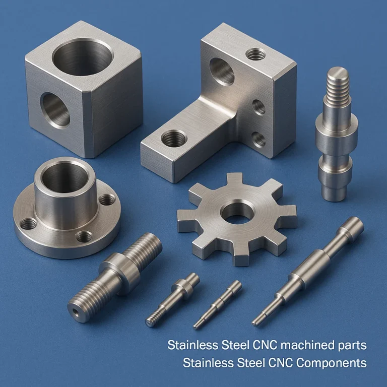
Stainless Steel Stamping, Stainless Steel Stamped parts, Stainless Steel Stamped Components, Pressed Stainless Steel parts and Components: Process Fundamentals and Metallurgical Considerations
Core Process Overview
Stainless steel stamping is a cold-working metal forming process that employs precision dies and mechanical or hydraulic presses operating at forces ranging from 25 tons to 800 tons to permanently deform stainless steel sheet, strip, or coil material into specified geometries. The process encompasses multiple forming operations including blanking, piercing, bending, drawing, coining, embossing, and flanging, often performed sequentially within progressive die systems operating at speeds of 30-400 strokes per minute.
Material Flow and Work Hardening Dynamics
Unlike carbon steel, stainless steel alloys exhibit significant work hardening (strain hardening) during cold forming operations. Austenitic grades (300 series) can experience yield strength increases of 200-300% during stamping, with the rate of work hardening expressed by the strain hardening exponent (n-value). Type 304 stainless steel typically exhibits an n-value of 0.45-0.55, while Type 316 ranges from 0.50-0.60, affecting springback calculations and bend allowance factors.
The work hardening behavior follows the power law relationship: σ = K(ε^n), where σ represents true stress, K is the strength coefficient (900-1400 MPa for austenitic stainless), ε is true strain, and n is the strain hardening exponent.
Springback Compensation and Elastic Recovery
Stainless steel’s high yield strength and elastic modulus (193 GPa for austenitic grades) necessitate precise springback compensation in die design. Springback angles typically range from 2-8 degrees depending on material grade, thickness, and bend radius. Our engineering team employs finite element analysis (FEA) using DYNAFORM or AutoForm software to predict springback behavior and incorporate overbend angles of 1.5-2.0 times the anticipated springback into die geometries.
The springback factor (Ks) is calculated as: Ks = (180° – θf)/(180° – θi), where θf is the final angle and θi is the initial formed angle.
Tooling Materials and Surface Treatments
Progressive dies and transfer tooling for stainless steel stamping utilize D2 tool steel (58-62 HRC), A2 tool steel for shock resistance, or carbide inserts for ultra-high-volume applications exceeding 5 million impressions. Critical punch and die surfaces undergo cryogenic treatment followed by physical vapor deposition (PVD) of titanium nitride (TiN), titanium carbonitride (TiCN), or chromium nitride (CrN) coatings to achieve surface hardness of 80-85 HRC and reduce galling, a common failure mode when forming austenitic stainless steels.
Die clearances are precisely maintained at 5-8% of material thickness for austenitic grades and 4-6% for ferritic grades to control burr formation and edge quality. Punch-to-die clearances are held to ±0.005mm using wire EDM and jig grinding operations.
Stainless Steel Stamped Parts: Engineering Specifications and Geometric Capabilities
Dimensional Capabilities and Tolerances
Our stamping facilities produce stainless steel parts with the following geometric parameters:
Material Thickness Range: 0.10mm – 6.35mm (0.004″ – 0.250″) Part Envelope: 5mm x 5mm minimum to 600mm x 800mm maximum Positional Tolerance: ±0.025mm to ±0.15mm depending on part geometry and material thickness Hole Diameter Tolerances: ±0.025mm for diameters >3.0mm; ±0.05mm for <3.0mm Flatness: 0.05mm per 100mm for parts <2mm thickness; 0.10mm per 100mm for heavier gauges Perpendicularity: Within 0.10mm over feature height Surface Finish: Ra 0.4μm to Ra 1.6μm as-stamped; Ra 0.2μm after electropolishing
Complex Feature Formation
Advanced stamping operations enable the production of intricate features including:
- Precision Holes and Slots: Minimum hole diameter of 0.8 times material thickness; slot widths down to 1.0mm with length-to-width ratios up to 10:1
- Embossed Features: Ribs, bosses, and strengthening beads with height-to-width ratios up to 0.75:1
- Drawn Shells: Draw depths up to 1.5 times blank diameter for shallow draws; specialized draw dies for depth-to-diameter ratios exceeding 2:1
- Formed Threads: Extruded tapped holes eliminating secondary operations, suitable for M2-M6 thread sizes in material thicknesses 0.8mm-3.0mm
- Coining and Sizing: Sub-micron dimensional control through bottom-dead-center densification at pressures of 2000-3000 MPa
Edge Quality and Burr Control
Sheared edges in stamped stainless steel parts exhibit characteristic zones: rollover (5-15% of thickness), burnish (30-60%), fracture (25-50%), and burr (5-20%). Our precision ground dies with maintained clearances produce predominantly burnished edges with burr heights <0.05mm. For critical applications requiring burr-free edges, we employ fine blanking technology operating at blanking pressures of 400-600 MPa with V-ring impingement forces and close die clearances of 0.5-1.0% material thickness.
Stainless Steel Stamped Components: Industry-Specific Manufacturing
Automotive Components
Fuel System Components: Stamped fuel rails, injector housings, and tank mounting brackets from Type 304L and 316L stainless steel meeting SAE J2227 corrosion resistance requirements. Parts undergo pressure testing to 1.5x operating pressure and leak testing at 10^-6 mbar·L/s helium leak rates.
Exhaust System Elements: Flanges, heat shields, and sensor bosses from Type 409, Type 439, or Type 441 ferritic stainless steels selected for high-temperature oxidation resistance up to 900°C. Components meet dimensional stability requirements after thermal cycling per SAE J2886.
Structural Brackets and Reinforcements: High-strength stamped components from lean duplex grades (LDX 2101) or Type 301 full-hard stainless steel providing tensile strengths of 1000-1200 MPa while maintaining formability for complex geometries.
Medical Device Manufacturing
Medical-grade stamped components utilize Type 316L or Type 316LVM (vacuum melted) stainless steel conforming to ASTM F138 and ISO 5832-1 standards. Critical considerations include:
- Surface Integrity: Ra <0.4μm with absence of embedded foreign material verified through SEM inspection
- Passivation: ASTM A967 compliant citric acid or nitric acid passivation achieving passive film thickness of 3-5nm
- Biocompatibility: ISO 10993 testing for cytotoxicity, sensitization, and irritation
- Traceability: Full material certification with heat lot tracking and process documentation
Typical medical stamped components include surgical instrument components, implantable device housings (cardiac rhythm management, neurostimulation), endoscopic tool parts, and diagnostic equipment elements.
Electronics and Telecommunications
EMI/RFI Shielding Components: Precision stamped shields, cans, and contact fingers from Type 301 or Type 304 stainless steel with specified electrical conductivity >1.4 MS/m and shielding effectiveness >60dB in the 1-10 GHz frequency range. Nickel or tin-over-nickel plating enhances conductivity and solderability.
Connector Components: Contact springs, terminals, and housing elements requiring spring temper material (1/4 Hard to Full Hard conditions) with controlled springback, contact force specifications of 50-500 grams-force, and insertion/extraction cycle life exceeding 10,000 operations.
Heat Dissipation Elements: Stamped heat sinks and thermal management components utilizing stainless steel’s thermal conductivity (16 W/m·K for Type 304) in applications requiring corrosion resistance superior to aluminum or copper.
Aerospace Applications
Aerospace stamped stainless components conform to AMS specifications including AMS 5510 (Type 301), AMS 5524 (Type 304L), and AMS 5653 (Type 316). Components undergo:
- Non-Destructive Testing: Fluorescent penetrant inspection per AMS 2647 or magnetic particle inspection for ferritic grades
- Dimensional Verification: 100% inspection using CMM equipment with measurement uncertainty <0.005mm
- Material Certification: Complete chemical composition analysis and mechanical property testing with certified test reports (CTR)
Applications include environmental control system components, hydraulic system fittings, structural brackets rated for -55°C to +250°C operational environments, and fastener components.
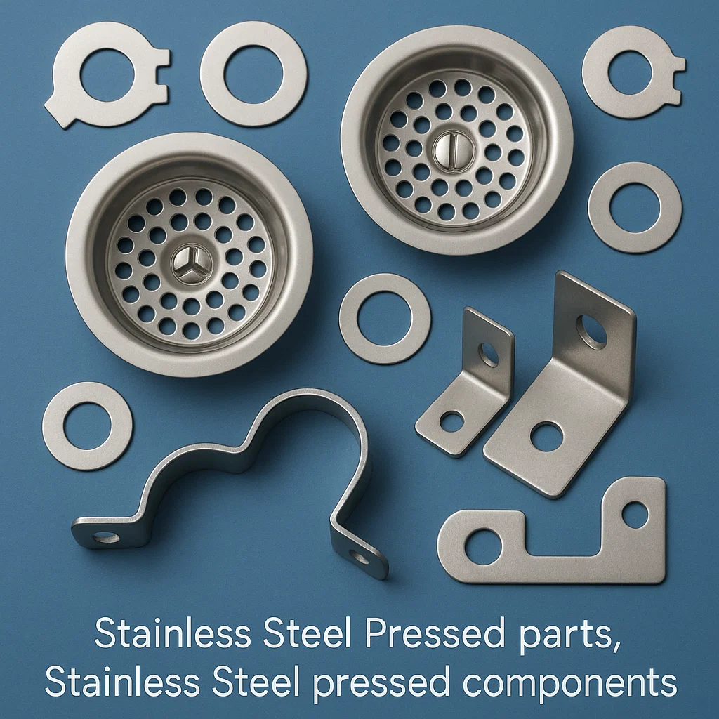
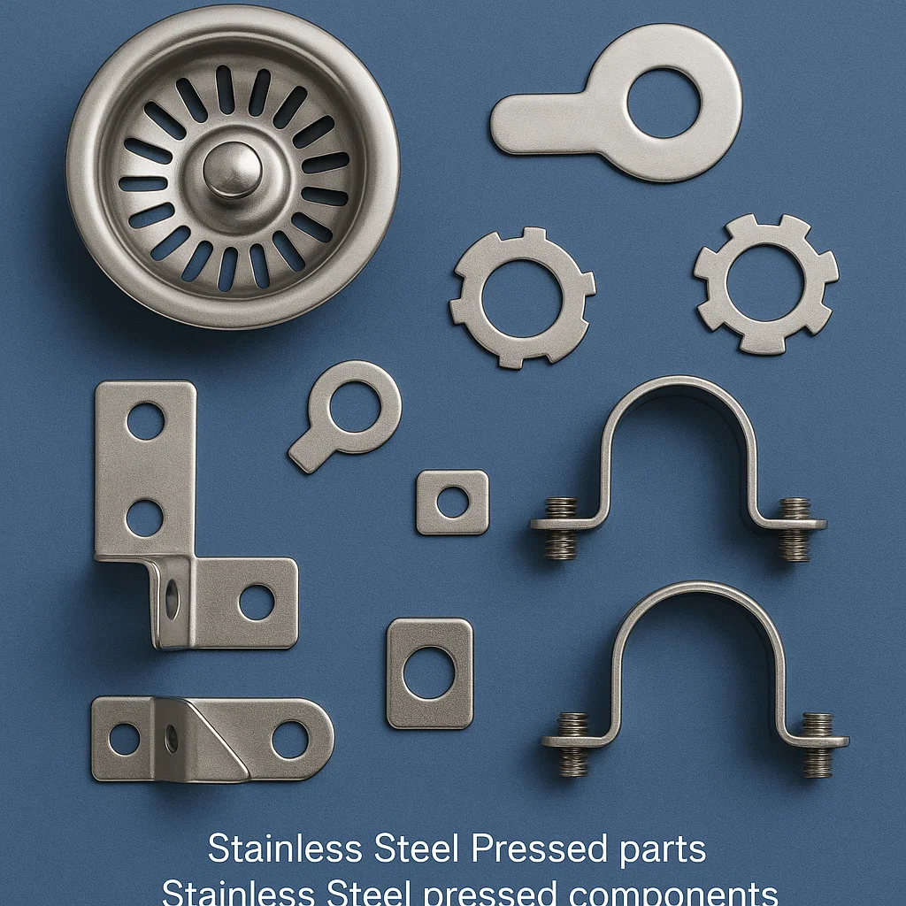
Stainless Steel Pressed Components: Deep Draw and Complex Forming Operations
Deep Drawing Process Mechanics
Deep drawing transforms flat stainless steel blanks into hollow, seamless components through plastic deformation over a punch while restraining material flow with a blank holder. The limiting draw ratio (LDR = blank diameter/punch diameter) for austenitic stainless steels ranges from 2.0 to 2.4 in single-draw operations, with multi-stage progressive draws achieving depth-to-diameter ratios exceeding 4:1.
Critical process parameters include:
Blank Holder Force (BHF): 30-40% of drawing force for austenitic grades, precisely controlled via nitrogen gas springs or servo-driven cushion systems to prevent wrinkling while avoiding excessive thinning. BHF = k × π × (D² – d²) / 4 × σy, where k is the blank holder coefficient (0.015-0.025), D is blank diameter, d is punch diameter, and σy is material yield strength.
Drawing Speed: 10-50 mm/s for austenitic stainless steels; excessive speeds generate heat buildup degrading lubrication effectiveness and increasing galling risk.
Lubrication Systems: Chlorinated paraffin oils, phosphate conversion coatings with soap lubricants, or dry film lubricants (polyethylene, PTFE) for deep-draw applications. Coefficient of friction targets: μ = 0.08-0.12 for optimal material flow.
Punch and Die Radii: Punch nose radius typically 4-8 times material thickness; die entry radius 6-10 times thickness to manage strain distribution and prevent splitting.
Wall Thickness Distribution and Thinning
Stainless steel deep-drawn components experience non-uniform thickness distribution due to differential strain states. Maximum thinning occurs at the punch nose radius where material undergoes combined drawing and bending strains. Our process control maintains wall thickness variation within 10-15% of nominal, with minimum wall thickness meeting specification requirements.
Thinning percentage is approximated by: t = t₀ × (r₀/r)^n, where t₀ is initial thickness, r₀ is initial radius, r is final radius, and n is the strain hardening exponent.
For critical applications, we employ intermediate annealing operations at 1040-1120°C (austenitic grades) between draw stages to restore ductility, with subsequent pickling in HNO₃/HF solutions to remove heat scale.
Hydroforming and Rubber Pad Forming
For low to medium volume production (100-10,000 pieces annually), we utilize flexible die forming technologies:
Hydroforming: Fluid pressure (40-150 MPa) forces stainless steel sheet against a single-sided die, ideal for complex contours, asymmetric shapes, and large shallow parts with minimal tool investment. Achieves uniform pressure distribution and superior surface quality (Ra <0.8μm).
Polyurethane Pad Forming (Guerin Process): 50-80 durometer Shore A polyurethane pads replace the matching die, suitable for short-run stampings, prototypes, and parts requiring frequent design iterations. Economical for quantities <5,000 pieces.
Stainless Steel Sheet Metal Parts: Integration of Secondary Operations
Precision Machining Integration
Post-stamping secondary operations expand functional capabilities:
CNC Milling and Drilling: Achieving tight positional tolerances (±0.025mm) for features requiring precision beyond stamping capability, including threaded holes, counterbores, and milled pockets. Machining parameters optimized for work-hardened stampings: cutting speeds 40-60 m/min, feed rates 0.05-0.15 mm/rev, using carbide or ceramic tooling.
Tapping and Thread Forming: Metric and unified thread forms from M2-M12 (UNC #4-40 through 1/2-13), either cut threads in drilled holes or form threads in extruded holes for enhanced strength.
Reaming and Precision Boring: Final hole sizing to H7 or H8 tolerance grades, surface finishes to Ra 0.4μm for bearing surfaces, dowel pin locations, and precision alignment features.
Welding and Joining Technologies
Resistance Spot Welding: 120-1200 Joule energy input, electrode forces 200-600 kg, weld times 10-30 cycles for fusion bonding austenitic stainless steel assemblies. Minimum 2t shear strength, where t is thinner material thickness.
Laser Welding: Nd:YAG or fiber laser systems (1-6 kW) producing minimal heat-affected zones (0.5-1.5mm) with penetration depths up to 3mm. Ideal for precision assemblies requiring minimal distortion and cosmetic appearance.
TIG Welding (GTAW): Manual or automated TIG welding with ER308L or ER316L filler wire for structural joints, meeting AWS D1.6 or ASME Section IX qualification requirements.
Adhesive Bonding: Structural acrylic or epoxy adhesives (3M 2216, Loctite 9466) for hybrid joints combining mechanical stamped features with chemical bonding for vibration resistance and sealing.
Surface Finishing Treatments
Electropolishing: Anodic dissolution in phosphoric/sulfuric acid electrolyte removes 5-25μm surface layer, achieving mirror finishes (Ra 0.1-0.2μm), deburring sharp edges, and enhancing corrosion resistance through microstructural smoothing and chromium enrichment of passive layer.
Passivation: ASTM A967 citric acid (Method 5) or nitric acid (Method 3) immersion at 49-66°C for 20-60 minutes removes embedded iron particles and promotes uniform passive film formation. Validated through copper sulfate testing or electrochemical methods.
Mechanical Finishing: #4 brushed finish (Ra 0.4-0.8μm), #7 buffed finish (Ra 0.2-0.4μm), or #8 mirror finish (Ra <0.2μm) applied via abrasive belts, buffing wheels, or mass finishing systems.
PVD/DLC Coating: Physical vapor deposition of titanium nitride, chromium nitride, or diamond-like carbon for wear resistance, reduced friction (μ = 0.1-0.2), and enhanced surface hardness (1500-3000 HV).
Stainless Steel Pressing: Advanced Forming Technologies
Progressive Die Stamping Systems
Progressive dies incorporate multiple stations performing sequential operations as stainless steel strip advances through the die at precise pitch increments (typically 10-200mm). Modern progressive dies feature:
Station Configuration: 5-30 stations including pilot punches for registration accuracy, idle stations for material stress relief, and forming stations sequenced to optimize material flow and minimize distortion.
Carrier Strip Design: Web retention systems maintaining 10-20% strip connection until final cutoff, ensuring precise part location throughout forming sequence. Web width optimization balances material utilization (targeting >75% material efficiency) against structural integrity.
Sensor Integration: Electronic sensors monitoring strip feeding, part presence, scrap evacuation, and die protection. Servo feed systems achieve ±0.01mm feeding accuracy at speeds to 400 SPM.
Quick Die Change (QDC): Standardized die mounting systems enabling die changes in <15 minutes, utilizing automatic clamp systems, standardized die heights (300-420mm), and integrated connection manifolds for coolant, air, and sensors.
Transfer Stamping Systems
For larger stampings (>300mm dimensions) or complex three-dimensional forming, transfer press systems move individual blanks between press stations using mechanical fingers, magnetic transfer systems, or vacuum cup arrays. Transfer systems enable:
- Independent station timing and dwell optimization
- Multi-axis forming including side-action cams and angular punch movements
- Integration of in-die tapping, staking, and assembly operations
- Part-to-part transfer accuracy ±0.15mm with repeat positioning to ±0.05mm
Servo Press Technology
Servo-driven mechanical presses provide programmable slide motion profiles optimizing stainless steel forming:
Variable Speed Control: Reduced forming speeds (10-100 mm/s) during critical forming phases minimize thinning and springback while maximizing production speed during non-forming portions of stroke cycle.
Dwell Time Programming: Extended bottom-dead-center dwell (100-500 milliseconds) for coining operations, stress relief, and dimensional accuracy in work-hardening materials.
Energy Efficiency: Regenerative braking systems and motion profiling reduce energy consumption 20-40% versus conventional flywheel presses while eliminating flywheel speed variation affecting part consistency.
Link Motion Capability: Programmable slide velocity, acceleration, and position throughout stroke enable forming profiles impossible with conventional cam-driven presses.
Stainless Steel Material Grades: Selection Criteria and Formability Characteristics
Austenitic Stainless Steels (300 Series)
Type 301 (UNS S30100, 1.4310): 16-18% Cr, 6-8% Ni, 2% Mn
- Excellent work hardening characteristics enabling spring temper conditions (1/4H to Full Hard)
- Tensile strength range: 760 MPa (annealed) to 1900 MPa (Full Hard)
- Superior formability in annealed condition with elongation 50-60%
- Applications: Electrical enclosures, springs, structural components requiring high strength-to-weight ratio
- Forming recommendation: Anneal for deep drawing; use 1/4H or 1/2H for moderate forming with enhanced strength
Type 304/304L (UNS S30400/S30403, 1.4301/1.4307): 18-20% Cr, 8-10.5% Ni
- Industry standard austenitic grade balancing cost, formability, and corrosion resistance
- 304L variant (≤0.03% C) prevents intergranular corrosion in welded assemblies
- Elongation: 40-50% (annealed), excellent deep drawability
- Tensile strength: 515-620 MPa (annealed), 1400+ MPa after severe cold working
- Applications: Food processing equipment, chemical processing, architectural trim, automotive exhaust
- Forming recommendation: Ideal for complex stampings, progressive dies, deep-draw operations
Type 316/316L (UNS S31600/S31603, 1.4401/1.4404): 16-18% Cr, 10-14% Ni, 2-3% Mo
- Molybdenum addition provides superior resistance to chloride pitting and crevice corrosion
- Preferred for marine environments, chemical processing, pharmaceutical equipment
- Slightly lower formability than 304 due to higher alloy content and work hardening rate
- Applications: Medical devices, marine hardware, pharmaceutical production equipment
- Forming recommendation: Reduce forming speeds 10-15% versus 304; allow greater springback compensation
Type 321 (UNS S32100, 1.4541): 17-19% Cr, 9-12% Ni, 5×(C+N) Ti
- Titanium stabilization prevents carbide precipitation at elevated temperatures (425-815°C)
- Maintains corrosion resistance and mechanical properties after welding
- Applications: Aerospace exhaust systems, high-temperature chemical processing
- Forming recommendation: Similar to 304; titanium carbide inclusions may slightly increase die wear
Ferritic Stainless Steels (400 Series)
Type 409 (UNS S40900, 1.4512): 10.5-11.75% Cr, <0.5% Ni, Ti/Nb stabilized
- Cost-effective ferritic grade for automotive exhaust applications
- Limited formability versus austenitic grades; maximum draw ratio ~1.7:1
- Non-work-hardening; maintains consistent mechanical properties during forming
- Magnetic properties enable electromagnetic forming and magnetic transfer handling
- Applications: Exhaust systems, catalytic converter shells, muffler components
- Forming recommendation: Increase bend radii to 2-3t minimum; utilize intermediate annealing for multi-stage draws
Type 430 (UNS S43000, 1.4016): 16-18% Cr, non-stabilized ferritic
- General purpose ferritic grade with moderate formability and corrosion resistance
- Lower cost than austenitic grades; suitable for non-critical applications
- Prone to ridging in highly stretched areas; grain structure orientation affects surface appearance
- Applications: Appliance trim, automotive trim, indoor architectural elements
- Forming recommendation: Limit draw depths; orient rolling direction perpendicular to maximum stress for improved formability
Type 439 (UNS S43035, 1.4510): 17-19% Cr, Ti/Nb stabilized
- Enhanced high-temperature oxidation resistance versus Type 409
- Improved formability and weldability versus Type 430
- Applications: Automotive exhaust, industrial heat exchangers
- Forming recommendation: Similar constraints to Type 430 with slightly improved draw characteristics
Martensitic Stainless Steels
Type 410 (UNS S41000, 1.4006): 11.5-13.5% Cr, ≤0.15% C
- Hardenable through heat treatment to 50+ HRC
- Must be stamped in annealed condition (85-95 HRB) then heat treated
- Limited formability; suitable for shallow draws and simple bends
- Applications: Cutlery, valve trim, fasteners requiring corrosion resistance and high hardness
- Forming recommendation: Anneal to maximum softness; avoid tight bend radii; post-form heat treatment required
Type 420 (UNS S42000, 1.4021): 12-14% Cr, >0.15% C
- Higher carbon enables greater hardness (54-58 HRC) after heat treatment
- Very limited formability; primarily simple blanking and shallow forming
- Applications: Knife blades, surgical instruments, valve components
- Forming recommendation: Minimize forming operations; consider machining as alternative
Duplex and Lean Duplex Stainless Steels
Type 2205 (UNS S32205, 1.4462): 22% Cr, 5.5% Ni, 3% Mo
- Dual-phase microstructure (50% ferrite, 50% austenite) provides strength double that of Type 304
- Yield strength: 450-550 MPa; tensile strength: 650-880 MPa
- Moderate formability limited by high strength and work hardening
- Excellent corrosion resistance rivaling Type 316L at lower nickel content/cost
- Applications: Chemical processing, oil/gas extraction, marine structures
- Forming recommendation: Require higher tonnage presses; increase die clearances to 8-10%; expect greater springback
LDX 2101 (UNS S32101, 1.4162): 21.5% Cr, 1.5% Ni, 0.3% Mo, 5% Mn, 0.22% N
- “Lean” duplex with nitrogen strengthening replacing expensive nickel
- Excellent formability for duplex grade; suitable for cold heading and moderate drawing
- Yield strength: 530-700 MPa (significantly higher than 304 at similar cost)
- Applications: Structural components, transportation equipment, water systems
- Forming recommendation: Formability approaches Type 304 while providing superior strength; ideal for high-strength stampings
Precipitation Hardening Grades
17-4 PH (UNS S17400, 1.4542): 15.5% Cr, 4% Ni, 4% Cu, 0.3% Nb
- Stampable in solution-annealed condition (30-35 HRC)
- Age hardening treatment post-forming achieves 38-47 HRC
- Applications: Aerospace components, medical instruments, high-strength fasteners
- Forming recommendation: Form in solution-treated condition; age harden post-forming; complex shapes require specialized expertise
Typical Stamped Parts Produced
Component Categories and Specifications
Brackets and Mounting Hardware
- L-brackets, Z-brackets, complex multi-plane brackets
- Thickness range: 0.5mm – 4.0mm
- Material grades: Type 304, 316, LDX 2101
- Features: Multiple bends (up to 6 planes), mounting holes, embossed reinforcements
- Tolerances: ±0.15mm on bent dimensions, ±0.05mm on hole locations
- Volume: 1,000 to 5,000,000 pieces annually
Enclosures and Shields
- EMI/RFI shielding cans (rectangular, circular, custom contours)
- Equipment enclosures with integrated mounting features
- Thickness: 0.2mm – 1.5mm
- Material grades: Type 301 (spring temper), Type 304
- Features: Multiple bends, snap features, ventilation slots, PEM hardware integration
- Shielding effectiveness: >60dB attenuation at 1-10 GHz
- Surface finish: Electroless nickel, tin plating, or passivation
Deep Drawn Shells and Containers
- Cylindrical, rectangular, and irregular cross-section shells
- Draw depth-to-diameter ratios: 0.5:1 to 4:1 (multi-stage)
- Material grades: Type 304, 316L
- Wall thickness: 0.3mm – 2.5mm
- Features: Flanged rims, threaded inserts, precision internal features
- Applications: Medical device housings, fuel system components, sensor housings
Contact Springs and Electrical Components
- Cantilever springs, torsion springs, compression springs
- Material: Type 301 Full Hard, Type 302
- Thickness: 0.15mm – 0.8mm
- Spring force accuracy: ±10% from nominal
- Cycle life: 10,000 – 1,000,000 operations
- Plating: Gold, nickel, tin for electrical conductivity
Washers, Shims, and Spacers
- Flat washers, wave washers, Belleville washers
- Inner diameter: 2mm – 100mm
- Thickness: 0.1mm – 3.0mm
- Material grades: Type 301, 304, 316
- Tolerances: ±0.05mm on critical dimensions
- Surface finish: Passivated or electropolished
Flanges and Fittings
- Pipe flanges, tube fittings, hydraulic flanges
- Sizes: DN10 (NPS 3/8″) to DN150 (NPS 6″)
- Material grades: Type 304L, 316L (wetted components)
- Features: Precision bolt circles, raised faces, seal grooves
- Pressure ratings: Up to Class 300 (5000 psi)
- Compliance: ASME B16.5, DIN 2527
Heat Sinks and Thermal Management Components
- Finned heat sinks, stamped thermal spreaders
- Fin pitch: 1.5mm – 10mm
- Material: Type 304, 430 (high thermal conductivity orientation)
- Thermal performance: Verified through CFD and thermal testing
- Surface treatment: Black oxide, anodize (hybrid aluminum-stainless designs)
Automotive Components
- Fuel rail mounting brackets (Type 304L)
- Exhaust flanges and heat shields (Type 409, 439)
- Sensor mounting brackets (Type 304)
- Seatbelt components (Type 301, HSLA stainless)
- Trim and decorative elements (Type 430, Type 304 #4 finish)
Medical Device Components
- Surgical instrument components (Type 316L, 420)
- Implantable device housings (Type 316LVM per ASTM F138)
- Diagnostic equipment parts (Type 304L, passivated)
- Sterilization tray components (Type 304)
- Compliance: ISO 13485, FDA 21 CFR Part 820
Applications Across Industries
Food and Beverage Processing
Stainless steel stampings meet FDA 21 CFR 177.2600 and EU 1935/2004 requirements for food contact. Type 304 and 316L components include mixing system baffles, tank mounting hardware, sanitary pipe fittings, conveyor system elements, and valve components. All parts achieve surface finishes ≤0.8μm Ra ensuring cleanability and preventing bacterial harboring. Regular passivation maintains hygienic surfaces meeting 3-A Sanitary Standards.
Chemical and Petrochemical
Corrosion-resistant stampings for aggressive environments utilize Type 316L (chloride resistance), duplex 2205 (high-strength, enhanced chloride resistance), and Type 321 (high-temperature stability). Components include reactor vessel internals, heat exchanger components, pump housings, valve trim, and instrumentation mounting hardware rated for temperatures to 400°C and pressures to 10,000 psi. Material selection per NACE MR0175/ISO 15156 for sour service applications.
Marine and Offshore
Type 316L and duplex stainless stampings resist seawater corrosion in boat hardware, navigation equipment housings, deck fittings, and offshore platform components. Pitting resistance equivalent number (PREN = %Cr + 3.3×%Mo + 16×%N) exceeds 40 for critical components ensuring >20-year service life in marine atmospheres. Salt spray testing per ASTM B117 validates 1000+ hours without red rust.
Pharmaceutical Manufacturing
Clean-room compatible stampings manufactured under ISO Class 8 conditions using Type 316L material with full traceability. Components include equipment mounting hardware, product contact surfaces, filling line components, and process vessel fittings. Electropolished surfaces achieve <0.4μm Ra preventing product adherence and enabling clean-in-place (CIP) validation. Bioburden testing confirms <10 CFU/100cm² surface contamination.
Aerospace and Defense
AS9100D certified production of flight-critical components from AMS-specification stainless steels. Environmental control system components, hydraulic system elements, fasteners, and structural brackets undergo 100% dimensional inspection, non-destructive testing, and material certification with full lot traceability. Components qualified for -55°C to +250°C operational environments with vibration resistance per MIL-STD-810 testing.
Electronics and Telecommunications
Precision stampings for 5G infrastructure, data center equipment, consumer electronics, and industrial controls. EMI shielding effectiveness verified through MIL-STD-285 or IEEE 299 testing methodologies. Contact springs meet insertion force specifications ±10 grams-force with cycle life validation through accelerated testing (>50,000 cycles). Tight tolerances (±0.025mm) ensure reliable automated assembly.
Renewable Energy
Stainless stampings in solar panel mounting systems (Type 304, 316), wind turbine components (duplex 2205), and battery system hardware (Type 316L) provide 25+ year service life. Components resist atmospheric corrosion, thermal cycling (-40°C to +90°C), and mechanical stresses. Material selection optimized for lifecycle cost considering initial investment and maintenance requirements.
HVAC and Building Systems
Architectural-grade stainless stampings including ductwork components, equipment mounting brackets, grilles and diffusers, and structural elements. Type 304 #4 brushed finish provides aesthetic appeal with corrosion resistance. Stampings meet building code requirements including seismic ratings and fire resistance classifications.
ISO 9001:2015 Quality Management System
Certification Scope and Implementation
Our manufacturing facilities maintain ISO 9001:2015 certification through accredited third-party auditors with annual surveillance audits and tri-annual recertification. The Quality Management System (QMS) encompasses:
Process-Based Approach: Identification of 42 core processes across product realization, support processes, and management processes with defined inputs, outputs, controls, and performance metrics.
Risk-Based Thinking: Systematic risk assessment using FMEA (Failure Mode and Effects Analysis) methodologies evaluating process risks with Risk Priority Numbers (RPN) and implementing controls for all risks with RPN >100.
Customer Focus: VOC (Voice of Customer) capture through structured feedback mechanisms, complaint tracking with 100% investigation and root cause analysis, and customer satisfaction surveys achieving >95% satisfaction ratings.
Continuous Improvement: Documented improvement projects reducing defect rates 15-20% annually, scrap reduction initiatives, and process capability improvements targeting Cpk >1.67 for critical characteristics.
Quality Control Infrastructure
Incoming Material Inspection: 100% certification review for all stainless steel coil and sheet with random sampling (MIL-STD-105E, AQL 1.0) for dimensional verification, surface quality assessment, and chemical composition verification through XRF analysis. Material traceability maintained from steel mill heat lot through finished component lot numbers.
In-Process Inspection: Statistical process control (SPC) monitoring of critical dimensions with control charts (X-bar, R-charts) at 1-4 hour intervals depending on process stability. Automated optical inspection (AOI) systems for 100% inspection of hole locations, edge quality, and dimensional conformance on high-volume progressive die operations.
First Article Inspection (FAI): Complete dimensional inspection per AS9102 methodology for all new programs, engineering changes, and annual revalidation. FAI reports document conformance to all drawing requirements using CMM equipment with documented measurement uncertainty.
Final Inspection: 100% visual inspection for cosmetic defects, dimensional sampling per production control plan (typically n=5 per lot), and functional testing where applicable. Non-conforming material segregated in designated quarantine areas with root cause investigation and corrective action implementation.
Measurement and Testing Capabilities
Dimensional Metrology:
- Coordinate Measuring Machines (CMM): 0.003mm measurement accuracy, 800mm x 1200mm x 600mm envelope
- Vision Measurement Systems: 0.005mm optical resolution for 2D dimensional inspection
- Height Gauges and Indicator Stands: 0.01mm resolution for production floor verification
- Micrometers and Calipers: Calibrated ±0.005mm, calibration intervals every 90 days
- Pin Gauges and Gauge Blocks: ASME B89.1.9 Grade AS-1 reference standards
Material Testing:
- Hardness Testing: Rockwell, Brinell, and Vickers hardness per ASTM E18, E10, E384
- Tensile Testing: Universal testing machine 100kN capacity per ASTM E8
- Surface Roughness: Stylus profilometry 0.01μm Ra resolution per ASME B46.1
- Coating Thickness: Eddy current and magnetic induction coating thickness gauges
- XRF Alloy Verification: Positive material identification for grade verification
Non-Destructive Testing:
- Fluorescent Penetrant Inspection per ASTM E1417 (Level II certified technicians)
- Magnetic Particle Inspection for ferritic/martensitic grades
- Ultrasonic Testing for internal defect detection in thick sections
- Radiographic Inspection for welded assemblies (when applicable)
Calibration and Traceability
All measurement and test equipment calibrated to NIST-traceable standards at documented intervals (typically 90-365 days depending on equipment type and usage frequency). Calibration records maintained in metrology database with automatic notification 30 days prior to expiration. Out-of-tolerance equipment immediately quarantined with investigation of all measurements performed since last valid calibration.
Document Control and Record Retention
Engineering drawings, specifications, work instructions, and quality records maintained in electronic document management system with revision control, approval workflows, and obsolete document prevention. Quality records retained minimum 10 years for commercial products, 25+ years for aerospace applications, and permanently for medical devices.
Supplier Quality Management
Approved supplier list (ASL) maintained with annual performance evaluation across quality, delivery, and cost metrics. Stainless steel suppliers required to maintain ISO 9001 certification or equivalent QMS with material certifications traceable to steel mill test reports. New supplier qualification includes facility audit, sample evaluation, and ongoing performance monitoring.
Internal Audit Program
Annual internal audit schedule covering all QMS processes with trained internal auditors. Audit findings classified by severity with mandatory corrective action timelines (major findings: 30 days, minor findings: 90 days). Management review conducted quarterly evaluating QMS effectiveness and improvement opportunities.
Technical Q&A: Stainless Steel Stamping
Material Selection and Design
Q: How do I select the appropriate stainless steel grade for my stamped component?
A: Material selection depends on corrosion environment, mechanical property requirements, formability needs, and cost constraints. For general corrosion resistance without chloride exposure, Type 304 provides optimal balance. Marine environments, chemical processing, or chloride exposure necessitate Type 316L with molybdenum addition. Applications requiring high strength-to-weight ratio benefit from duplex grades (2205, LDX 2101) offering yield strengths double austenitic grades. Cost-sensitive automotive exhaust applications utilize ferritic Type 409 or 439. Medical implant devices mandate Type 316LVM per ASTM F138. Consult with our metallurgy team for application-specific recommendations considering lifecycle costs and performance requirements.
Q: What minimum bend radius should be specified for stainless steel stampings?
A: Minimum bend radius correlates with material thickness, hardness, and grain direction. Conservative design guidelines specify inside bend radius of 1.5-2.0 times material thickness for austenitic grades (304, 316) in annealed condition. Ferritic grades (430, 409) require larger radii: 2.5-3.0 times thickness. Work-hardened tempers (1/4H, 1/2H, Full Hard) necessitate proportionally larger radii: multiply annealed recommendations by 1.5-2.5×. Bending perpendicular to rolling direction enables tighter radii than parallel orientation. Critically stressed applications should specify 3-4t radii eliminating microcracks. Our engineering team validates bend radii through prototyping and strain analysis ensuring 100,000+ cycle fatigue life where applicable.
Q: How does work hardening affect stainless steel stamped components?
A: Cold working during stamping significantly increases yield and tensile strength while reducing ductility. Type 304 austenitic stainless can achieve tensile strengths exceeding 1400 MPa (versus 515 MPa annealed) through progressive work hardening. This phenomenon enables spring temper conditions (1/4 Hard, 1/2 Hard, Full Hard) for components requiring enhanced strength. However, work hardening complicates multi-stage forming as material becomes progressively harder to form. Deep-draw operations may require intermediate annealing between stages. Ferritic grades exhibit minimal work hardening, maintaining consistent properties throughout forming. Duplex grades show moderate work hardening. Specify annealed material for maximum formability; utilize tempered conditions when finished component requires enhanced mechanical properties. Our process engineers optimize forming sequences accounting for work hardening behavior.
Q: What tolerances are achievable in stainless steel stamping operations?
A: Achievable tolerances depend on material thickness, part geometry, forming complexity, and quality requirements. Standard production tolerances for hole locations: ±0.08mm for material <1.0mm thick, ±0.10mm for 1.0-2.0mm, ±0.15mm for >2.0mm thickness. Bend location tolerances: ±0.15mm typical, ±0.08mm with precision tooling. Overall part dimensions: ±0.15mm standard, ±0.05mm achievable through progressive die design with guided strippers. Flatness: 0.10mm per 100mm for standard parts, 0.05mm per 100mm with flattening operations. Tighter tolerances require secondary operations (machining, grinding) or fine blanking technology. High-volume production enables tighter statistical tolerances through process optimization and SPC monitoring. Submit detailed drawings for tolerance capability assessment specific to your application.
Process Capabilities
Q: What is the maximum part size capable of being stamped?
A: Our stamping equipment accommodates parts up to 800mm × 600mm in progressive die operations and 1200mm × 800mm in transfer press or single-stage forming. Material thickness capacity ranges 0.10mm to 6.35mm depending on part geometry and required features. Press tonnage available: 25 tons (small precision parts) to 800 tons (large heavy-gauge stampings). Larger assemblies can be manufactured as multiple stampings with secondary welding or mechanical assembly. Discuss oversized requirements with our engineering team for alternative manufacturing approaches including hydroforming, multi-stage forming, or weldment designs.
Q: Can stainless steel stampings be manufactured with threaded holes?
A: Yes, multiple approaches exist for threaded features. Form taps extruded into stamped material create 60-80% thread engagement for M2-M6 sizes in material thickness 0.8mm-3.0mm. This eliminates secondary tapping operations and enhances thread strength through cold-formed material. Alternatively, holes can be pierced during stamping with subsequent CNC tapping providing full 100% thread engagement for larger sizes (M8-M12) or critical applications. PEM self-clinching threaded inserts installed via press-fit provide reusable threads in thin gauge material. Flow-forming operations create extruded bosses enabling threads in sheet metal without additional hardware. Select approach based on thread size, material thickness, assembly/disassembly frequency, and cost optimization. Our design-for-manufacturing review recommends optimal threading methodology.
Q: How are tight tolerances maintained in high-volume progressive die stamping?
A: Progressive die tolerance control requires precision tool design, statistical process control, and preventive maintenance. Dies manufactured via wire EDM achieve ±0.005mm accuracy in critical features. Guided stripper plates maintain material alignment throughout die progression. Servo feed systems deliver strip positioning accuracy ±0.01mm. Hardened die inserts and PVD coatings minimize wear affecting dimensional stability. SPC monitoring with control charts identifies process drift before out-of-tolerance parts occur. Dimensional sampling every 1-4 hours with immediate corrective action maintains Cpk >1.67 for critical dimensions. Preventive maintenance schedules include die inspection every 50,000-100,000 hits with punch sharpening, clearance verification, and spring replacement. Automated optical inspection systems provide 100% dimensional verification on critical features. Temperature-controlled facilities (±2°C) eliminate thermal expansion affecting precision. Our quality system ensures consistent part-to-part repeatability throughout production runs exceeding 10 million pieces.
Q: What surface finishes are available for stainless steel stampings?
A: Surface finishes range from as-rolled material to mirror polish. Standard mill finishes include 2B (smooth, moderately reflective cold-rolled finish most common for stampings), 2D (dull, non-reflective), #4 brushed (directional satin finish, Ra 0.4-0.8μm), and BA (bright annealed, reflective). Post-stamping finishing includes:
- Passivation: ASTM A967 citric or nitric acid treatment removing free iron, enhancing corrosion resistance
- Electropolishing: Anodic dissolution producing Ra 0.1-0.2μm mirror finish, superior corrosion resistance, deburring
- Mechanical Polishing: #7 buffed finish (Ra 0.2-0.4μm) or #8 mirror finish (Ra <0.2μm)
- Mass Finishing: Vibratory or centrifugal finishing for deburring and surface conditioning
- Coatings: Electroless nickel, PVD (TiN, CrN), powder coating, PTFE for specific functional requirements
- Chemical Treatments: Black oxide, colored passivation layers for aesthetic differentiation
Surface finish selection should balance functional requirements (cleanability, corrosion resistance, friction), aesthetic needs, and cost implications. Consult regarding optimal finishing process for your application.
Quality and Compliance
Q: How is material traceability maintained through the manufacturing process?
A: Complete traceability begins with incoming material certification documenting steel mill heat lot, chemical composition (spectrographic analysis), mechanical properties (tensile testing), and compliance to specifications (ASTM A240, EN 10088). Material receiving inspection assigns internal lot numbers linked to mill certifications stored in ERP system. Coil/sheet material segregated by grade and heat lot in inventory. Production work orders specify material lot requirements with barcode scanning confirming correct material selection. Stamped components marked with lot codes via laser etching, ink stamping, or tag attachment. Finished component packaging includes certificates of compliance documenting material lot, production date, inspection results, and dimensional conformance. Traceability maintained through customer serialization when specified. Medical device components and aerospace parts include full material test reports with component shipments. Traceability records retained permanently enabling root cause investigation of field issues and regulatory compliance.
Q: What certifications accompany stamped stainless steel components?
A: Standard commercial shipments include:
- Certificate of Compliance documenting conformance to drawing requirements
- Material certifications (steel mill test reports) for material chemical and mechanical properties
- Dimensional inspection reports for first article and periodic sampling
- Surface finish verification (when specified)
- Functional test results (when applicable)
Enhanced certifications available:
- PPAP (Production Part Approval Process) documentation per AIAG standards
- FAI (First Article Inspection) per AS9102 for aerospace applications
- Material test reports per EN 10204 3.1 or 3.2
- NACE MR0175 compliance documentation for sour service
- FDA compliance letters for food contact or medical applications
- RoHS/REACH compliance declarations
- Country of origin certifications
Specify required documentation during quotation for inclusion in contract terms and piece-price.
Q: How are defects prevented and controlled in stamped components?
A: Comprehensive defect prevention strategies include:
Design Phase: Design-for-Manufacturing (DFM) review identifying potential forming issues, tolerance concerns, and process limitations. Finite element analysis simulating material flow, thinning, and springback. Prototype tooling validation before production die construction.
Tooling Phase: Precision die manufacturing via wire EDM achieving ±0.005mm accuracy. Die simulation software optimizing material flow and stress distribution. First-off sample approval confirming dimensional conformance and surface quality.
Production Phase: SPC monitoring with X-bar and R-charts identifying process drift. Automated inspection systems for 100% verification of critical features. Operator training and visual aids depicting acceptable/unacceptable conditions. Preventive maintenance schedules minimizing die wear-related defects.
Inspection Phase: Multi-level inspection including in-process checks, roving quality audits, and final inspection. Non-conforming material quarantine with root cause analysis. Statistical sampling per ISO 2859 (AQL methodology) for high-volume production.
Our defect rates consistently achieve <100 PPM (0.01%) for critical characteristics through disciplined process control and continuous improvement culture.
Conclusion
Stainless steel stamping represents a sophisticated intersection of materials science, precision tooling, and advanced manufacturing processes. Successful implementation requires deep understanding of alloy metallurgy, forming mechanics, quality systems, and application-specific requirements. Our ISO 9001:2015 certified facilities combine state-of-the-art equipment, experienced engineering personnel, and rigorous quality protocols to deliver precision stampings meeting the most demanding specifications across automotive, medical, aerospace, electronics, and industrial sectors.
From simple brackets to complex progressive die stampings, from ferritic exhaust components to medical-grade 316LVM implantable device housings, our capabilities span the complete spectrum of stainless steel forming technologies. We invite engineering collaboration during the design phase, ensuring optimal material selection, formability analysis, tolerance optimization, and lifecycle cost effectiveness.
Contact our technical sales team to discuss your stainless steel stamping requirements. Provide component drawings, annual volume projections, quality specifications, and delivery requirements for comprehensive quotation including DFM analysis, tooling investment, piece-price, and lead times. Our engineering staff stands ready to transform your concepts into precision-manufactured reality.