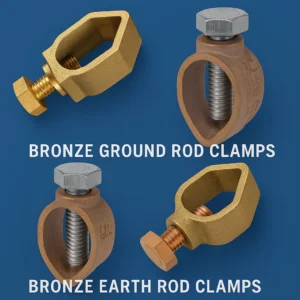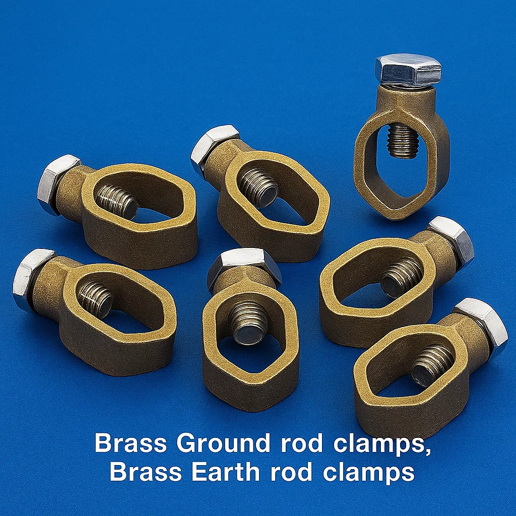
Brass Ground Rod Clamps & Brass Earth Rod Clamps, Earthing Rod Clamps, Bronze Ground Rod clamps
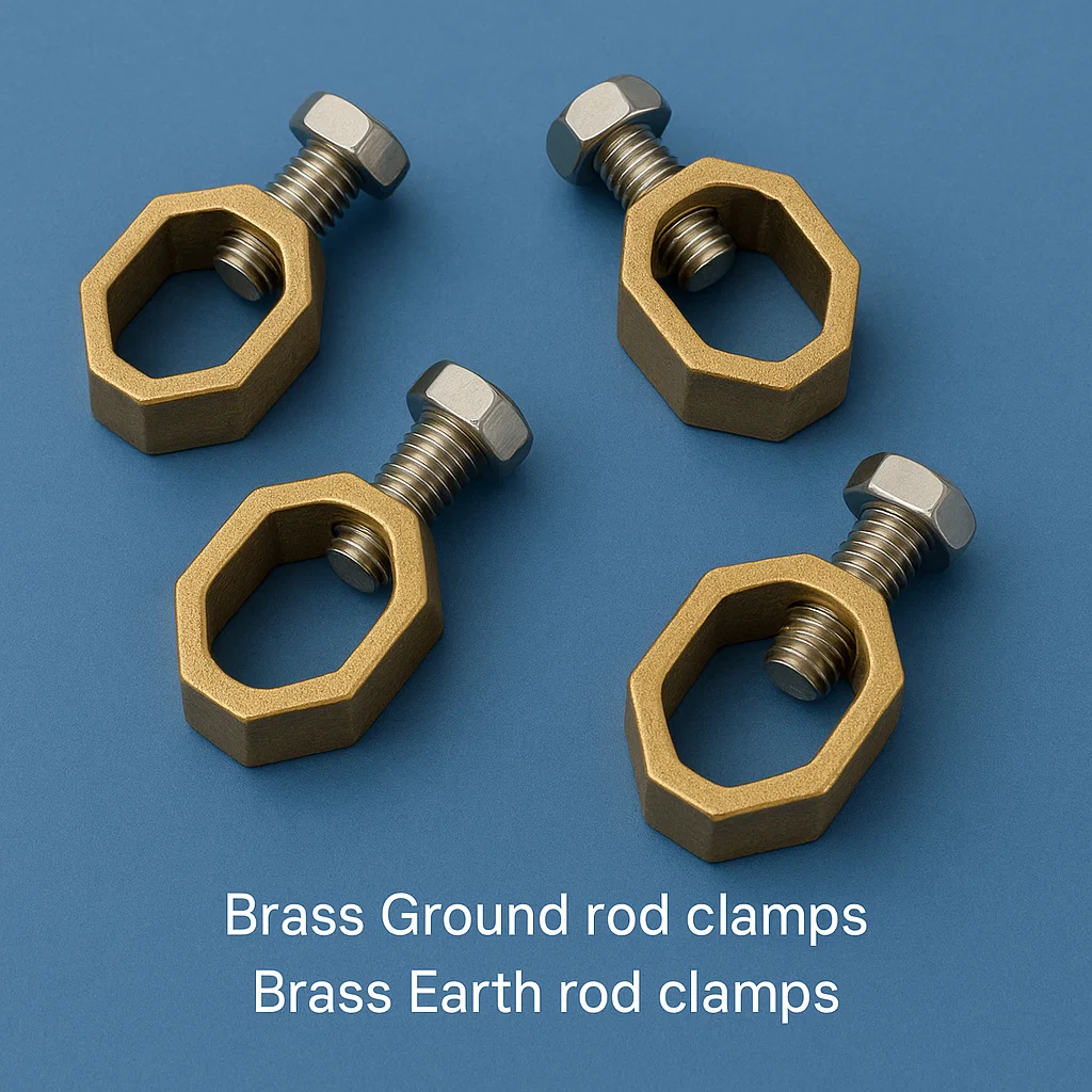
Sizes: 1/2″, 5/8″ and 3/4″ Ground rod clamps, Earth rod clamps
Table of Contents
- Overview and Terminology
- Technical Specifications
- Materials and Construction
- Types and Classifications
- Electrical Characteristics
- Installation Procedures
- Standards and Compliance
- Applications and Use Cases
- Performance Optimization
- Maintenance and Inspection
- Troubleshooting and Diagnostics
- Safety Considerations
Overview and Terminology
Brass ground rod clamps and brass earth rod clamps are critical electrical grounding components designed to establish secure, low-resistance connections between grounding conductors and driven ground rods (earth electrodes). These specialized electrical hardware devices ensure reliable electrical continuity in grounding systems, providing essential safety and system protection functions.
Key Terminology
- Ground Rod Clamp: Primary connection device between grounding conductor and ground rod
- Earth Rod Clamp: International terminology equivalent to ground rod clamp
- Grounding Electrode Conductor (GEC): Wire or cable connected to the clamp
- Ground Rod: Driven electrode, typically copper-bonded steel or stainless steel
- Electrode: Any conductor used to establish electrical contact with earth
- Bonding: Permanent joining of metallic parts to form electrically conductive path
Technical Specifications
Dimensional Standards
- Conductor Size Range: #14 AWG to 4/0 AWG (2.1mm² to 107mm²)
- Ground Rod Compatibility: 1/2″, 5/8″, 3/4″, 1″ diameter rods
- Thread Specifications:
- Hex head bolts: 1/4″-20, 5/16″-18, 3/8″-16 UNC
- Socket head cap screws: M6, M8, M10 metric threading
- Overall Dimensions: Varies by conductor size (typically 2″ to 4″ length)
- Clamping Surface Area: 0.75″ to 2.5″ contact length on rod
Electrical Ratings
- Current Carrying Capacity: 200A to 600A continuous
- Short Circuit Current Rating: 10kA to 65kA (varies by size)
- Contact Resistance: <50 microohms initial, <100 microohms after aging
- Voltage Rating: 600V AC/DC system applications
- Frequency Response: DC to 1MHz (for transient applications)
- Temperature Coefficient: 0.4% per °C resistance increase
Environmental Specifications
- Operating Temperature Range: -40°C to +85°C (-40°F to +185°F)
- Storage Temperature: -55°C to +100°C (-67°F to +212°F)
- Humidity Resistance: 95% RH non-condensing
- Salt Spray Resistance: 500+ hours per ASTM B117
- UV Resistance: ASTM G154 Type IV exposure
- Soil Corrosion Resistance: pH 4.0 to 9.0 compatibility
Materials and Construction
Brass Alloy Composition
Primary Alloy: C36000 Free-Cutting Brass
- Copper (Cu): 60-63%
- Zinc (Zn): 35.5-38.5%
- Lead (Pb): 2.5-3.7%
- Iron (Fe): ≤0.35%
- Other elements: ≤0.5%
Alternative Alloy: C37700 Forging Brass
- Copper (Cu): 59-62%
- Zinc (Zn): 37-40%
- Lead (Pb): 1.5-2.5%
- Enhanced machinability and corrosion resistance
Physical Properties
- Tensile Strength: 48,000-55,000 psi (331-379 MPa)
- Yield Strength: 18,000-25,000 psi (124-172 MPa)
- Elongation: 15-25% in 2 inches
- Hardness: 65-85 HRB (Rockwell B)
- Density: 8.53 g/cm³ (0.308 lb/in³)
- Electrical Conductivity: 26-28% IACS
- Thermal Conductivity: 120-130 W/m·K
Manufacturing Processes
- Forging: Hot forging for enhanced grain structure
- Machining: CNC precision machining for critical dimensions
- Threading: Cut or rolled threads per ASME B18.2.1
- Surface Treatment: Electroplating or chemical passivation
- Quality Control: 100% dimensional and electrical testing
Fastener Specifications
- Material: Grade 8 steel, stainless steel 316, or brass
- Coating: Zinc plating, tin plating, or bare finish
- Torque Specifications: 8-25 ft-lbs depending on size
- Anti-Seize Compound: Copper-based or zinc-rich formulations
Types and Classifications of Brass Ground rod clamps, Bronze Ground Rod clamps
Design Classifications
Type A: Bolted Ground Rod Clamps
- Configuration: Two-piece split design with hex head bolt
- Applications: Permanent installations, high current applications
- Conductor Range: #6 AWG to 4/0 AWG
- Rod Compatibility: 1/2″ to 1″ diameter
- Assembly Torque: 15-25 ft-lbs
- Contact Method: Direct compression clamping
Type B: Set Screw Ground Rod Clamps
- Configuration: One-piece body with socket head set screws
- Applications: Temporary installations, lower current applications
- Conductor Range: #14 AWG to #2 AWG
- Rod Compatibility: 1/2″ to 3/4″ diameter
- Assembly Torque: 8-15 ft-lbs
- Contact Method: Point contact pressure
Type C: Lay-In Ground Rod Clamps
- Configuration: Hinged or split design for easy installation
- Applications: Retrofit installations, field assembly
- Conductor Range: #10 AWG to #2/0 AWG
- Rod Compatibility: 3/8, 1/2″ , 5/8″ and 3/4″ diameter Ground rods
- Assembly Method: Snap-fit or hinged closure
- Contact Method: Spring-loaded compression
Type D: Irreversible Ground Rod Clamps
- Configuration: Permanent compression or welded connection
- Applications: Critical infrastructure, theft prevention
- Conductor Range: #6 AWG to 350 MCM
- Rod Compatibility: 5/8″ to 1″ diameter
- Installation: One-time compression tool required
- Contact Method: Cold welding or compression crimp
Specialty Configurations
Multi-Conductor Clamps
- Capability: 2-6 conductor terminations per clamp
- Applications: Complex grounding systems, panel grounding
- Insulation: Individual conductor isolation available
- Size Range: #12 AWG to #2/0 AWG per conductor
Insulated Ground Rod Clamps
- Insulation Material: Cross-linked polyethylene (XLPE)
- Voltage Rating: 15kV, 25kV, 35kV classes
- Applications: Underground distribution, pad-mount equipment
- Color Coding: Red, orange, yellow per voltage class
Submersible Ground Rod Clamps
- Enclosure Rating: IP68, NEMA 6P
- Applications: Underwater installations, flood-prone areas
- Sealing: O-ring and gasket sealed joints
- Materials: Marine-grade brass alloys, stainless steel hardware
Electrical Characteristics
Conductivity Analysis
Contact Resistance Factors:
- Material resistivity coefficient
- Contact surface area and pressure
- Surface oxidation and contamination
- Temperature effects and thermal cycling
- Galvanic compatibility between materials
Resistance Calculation: R_total = R_conductor + R_clamp + R_contact + R_rod
Where:
- R_conductor: Conductor resistance per NEC Chapter 9
- R_clamp: Clamp body resistance (typically <10 microohms)
- R_contact: Interface resistance (target <50 microohms)
- R_rod: Ground rod resistance (varies with soil conditions)
Current Carrying Capacity
Continuous Current Ratings (75°C conductor):
- #14 AWG: 20A (brass clamp rated for 25A)
- #12 AWG: 25A (brass clamp rated for 30A)
- #10 AWG: 35A (brass clamp rated for 40A)
- #8 AWG: 50A (brass clamp rated for 55A)
- #6 AWG: 65A (brass clamp rated for 75A)
- #4 AWG: 85A (brass clamp rated for 95A)
- #2 AWG: 115A (brass clamp rated for 130A)
- #1/0 AWG: 150A (brass clamp rated for 170A)
- #2/0 AWG: 175A (brass clamp rated for 195A)
- #4/0 AWG: 230A (brass clamp rated for 260A)
Fault Current Performance
Short Circuit Withstand Capability:
- Based on I²t withstand ratings
- Typical ratings: 10kA for 1 second (100 kA²s)
- Enhanced ratings: 65kA for 1 second (4225 kA²s)
- Asymmetrical fault consideration: 1.6x symmetrical rating
Arc Flash Considerations:
- Incident energy calculation per IEEE 1584
- Working distance and protective boundary determination
- Personal protective equipment (PPE) category assignment
Installation Procedures
Pre-Installation Requirements
Site Survey and Preparation
- Soil Resistivity Testing: Four-point Wenner method per IEEE 81
- Ground Rod Installation: Proper depth and spacing per NEC 250.53
- Conductor Routing: Minimize length, avoid sharp bends
- Environmental Assessment: Corrosion potential, moisture exposure
Tools and Materials
Required Tools:
- Torque wrench (calibrated to ±5%)
- Wire strippers and cable cutters
- File or emery cloth for surface preparation
- Digital multimeter with microohm capability
- Ground resistance tester (fall-of-potential method)
Installation Materials:
- Joint compound (oxide inhibitor)
- Stainless steel wire brush
- Weatherproof tape or heat shrink tubing
- Corrosion protection compound
- Safety barriers and warning labels
Installation Steps
Step 1: Conductor Preparation
- Strip conductor insulation 1/2″ beyond clamp requirements
- Clean conductor surface with wire brush to bright metal
- Apply thin coat of oxide inhibitor compound
- Inspect for nicks, cuts, or stress concentration points
Step 2: Clamp Assembly
- Disassemble clamp components and inspect for damage
- Clean all contact surfaces with degreasing solvent
- Apply anti-seize compound to threaded fasteners
- Pre-position clamp on ground rod at desired location
Step 3: Connection Assembly
- Insert conductor into clamp body ensuring full contact
- Apply specified torque in incremental steps (25%, 50%, 75%, 100%)
- Verify conductor cannot be withdrawn under moderate force
- Check for proper alignment and full surface contact
Step 4: Quality Verification
- Measure connection resistance with microohm meter
- Perform visual inspection for proper assembly
- Apply weatherproofing materials as required
- Document installation with photos and resistance measurements
Torque Specifications Table
| Conductor Size | Clamp Bolt Size | Initial Torque | Final Torque | Re-torque Schedule |
|---|---|---|---|---|
| #14-#10 AWG | 1/4″-20 | 6 ft-lbs | 8 ft-lbs | Annual |
| #8-#6 AWG | 5/16″-18 | 10 ft-lbs | 12 ft-lbs | Annual |
| #4-#2 AWG | 3/8″-16 | 15 ft-lbs | 18 ft-lbs | Bi-annual |
| #1/0-#4/0 AWG | 1/2″-13 | 20 ft-lbs | 25 ft-lbs | Bi-annual |
Standards and Compliance
National and International Standards
Electrical Standards
- ANSI/UL 467: Grounding and Bonding Equipment
- IEEE 80: Guide for Safety in AC Substation Grounding
- IEEE 81: Guide for Measuring Earth Resistivity, Ground Impedance
- IEC 61936-1: Power Installations Exceeding 1 kV AC
- IEC 62561: Lightning Protection System Components
Material Standards
- ASTM B134: Brass Wire, Rod, Bar, and Shapes
- ASTM B135: Seamless Brass Tube
- ASTM B16: Free-Cutting Brass Rod, Bar and Shapes
- SAE J461: Wrought and Cast Copper Alloys
Installation Standards
- NFPA 70 (NEC): National Electrical Code
- Article 250: Grounding and Bonding
- Section 250.8: Connection of Grounding and Bonding Equipment
- Section 250.53: Grounding Electrode System Installation
- IEEE 142: Recommended Practice for Grounding Industrial and Commercial Power Systems
- IEC 60364: Low-voltage electrical installations
Environmental and Safety Standards
- OSHA 29 CFR 1910.269: Electric Power Generation, Transmission, and Distribution
- NESC: National Electrical Safety Code
- RoHS Directive 2011/65/EU: Restriction of Hazardous Substances
- REACH Regulation: Chemical Safety Assessment
Certification Requirements
- UL Listing: Third-party safety certification
- CSA Certification: Canadian Standards Association approval
- CE Marking: European Conformity marking
- RoHS Compliance: Lead content disclosure and alternatives
Applications and Use Cases
Residential Applications
- Service Entrance Grounding: Main electrical panel grounding electrode conductor connection
- Supplemental Electrodes: Additional grounding points per NEC 250.53(A)(2)
- Equipment Grounding: Pool equipment, HVAC systems, generators
- Lightning Protection: Residential lightning rod systems per NFPA 780
Commercial Applications
- Building Grounding Systems: Multi-story office buildings, retail complexes
- Data Center Grounding: Computer room grounding grids, equipment grounding
- Telecommunications: Cell tower grounding, fiber optic installations
- Solar Installations: Photovoltaic system equipment grounding
Industrial Applications
- Manufacturing Facilities: Machine grounding, process equipment bonding
- Chemical Plants: Intrinsically safe area grounding, static dissipation
- Oil and Gas: Wellhead grounding, pipeline cathodic protection systems
- Mining Operations: Mobile equipment grounding, explosive atmosphere applications
Utility Applications
- Substation Grounding: High-voltage equipment grounding grids
- Distribution Systems: Pad-mount transformer grounding
- Transmission Lines: Tower grounding, guy wire connections
- Underground Systems: Manhole and vault grounding
Specialized Applications
- Marine Environments: Offshore platforms, shipboard systems
- Transportation: Railway signal systems, airport lighting
- Healthcare Facilities: Medical equipment grounding, patient safety
- Hazardous Locations: Class I, II, III area installations per NEC 500
Performance Optimization
Contact Resistance Minimization
Surface Preparation Techniques
- Mechanical Cleaning: Wire brushing to remove oxidation
- Chemical Cleaning: Solvent degreasing for oil contamination
- Abrasive Treatment: Fine abrasive for surface texture improvement
- Protective Coating: Thin-film antioxidants for long-term stability
Joint Compound Selection
- Zinc-Rich Compounds: Galvanic protection for dissimilar metals
- Copper-Based Compounds: Enhanced conductivity for copper systems
- Penetrating Oils: Water displacement and corrosion prevention
- Graphite Suspensions: High-temperature stability applications
Thermal Management
Heat Generation Sources:
- I²R losses in conductor and connection
- Contact resistance heating at interfaces
- Solar radiation heating in outdoor installations
- Arc flash energy during fault conditions
Cooling Enhancement Methods:
- Increased surface area through finning
- Heat sink attachment for high-current applications
- Ventilation improvement in enclosed spaces
- Thermal interface materials for heat spreading
Corrosion Prevention
Galvanic Compatibility Matrix
| Material 1 | Material 2 | Compatibility | Recommended Action |
|---|---|---|---|
| Brass | Copper | Excellent | Direct connection |
| Brass | Steel | Fair | Protective coating |
| Brass | Aluminum | Poor | Isolation required |
| Brass | Stainless | Good | Monitor periodically |
Protective Measures
- Cathodic Protection: For below-grade installations
- Barrier Coatings: Epoxy or polyurethane systems
- Sacrificial Anodes: Zinc or magnesium anodes for severe environments
- Environmental Barriers: Moisture exclusion and pH control
Environmental Considerations
- Soil Chemistry: pH, moisture content, salt concentration
- Atmospheric Exposure: Industrial pollutants, marine environments
- Temperature Cycling: Thermal expansion/contraction effects
- UV Degradation: Polymer component aging
Maintenance and Inspection
Inspection Schedule
Initial Inspection (30 days post-installation):
- Visual examination for proper assembly
- Resistance measurement and comparison to baseline
- Torque verification of all fasteners
- Environmental protection integrity check
Routine Inspection (Annual):
- Connection resistance trending analysis
- Visual inspection for corrosion, damage, or loosening
- Fastener re-torquing per manufacturer specifications
- Ground system impedance measurement
Detailed Inspection (5-year intervals):
- Complete disassembly and cleaning
- Component replacement assessment
- Soil resistivity re-measurement
- Ground electrode integrity verification
Diagnostic Testing
Contact Resistance Testing
Equipment Required:
- Microohm meter (1 microohm resolution minimum)
- Kelvin test leads for accurate measurement
- Temperature compensation capability
- Data logging for trend analysis
Test Procedure:
- De-energize circuit and verify safe working conditions
- Connect test leads using proper Kelvin technique
- Apply test current (10-100A for accuracy)
- Record resistance value and ambient temperature
- Compare to baseline and acceptance criteria
Acceptance Criteria:
- New installation: <50 microohms
- Routine maintenance: <100 microohms
- Corrective action: >150 microohms
Ground Resistance Testing
Fall-of-Potential Method:
- Current electrode placement: 2.5× rod spacing minimum
- Potential electrode: 62% of current electrode distance
- Multiple measurements with varying potential electrode positions
- Soil resistivity correlation with seasonal variations
Clamp-On Testing Method:
- Non-intrusive testing of in-service systems
- Multiple ground electrode requirements
- Loop resistance measurement and calculation
- Validation with conventional methods recommended
Troubleshooting Guide
High Contact Resistance Issues
Potential Causes:
- Oxidation or corrosion at contact surfaces
- Insufficient contact pressure (loose hardware)
- Contamination from dirt, grease, or moisture
- Galvanic corrosion between dissimilar metals
Corrective Actions:
- Disassemble connection and inspect components
- Clean contact surfaces with appropriate methods
- Apply fresh joint compound or protective coating
- Re-assemble with proper torque specifications
- Implement enhanced corrosion protection measures
Mechanical Failure Analysis
Common Failure Modes:
- Fastener corrosion and thread damage
- Clamp body cracking from over-torquing
- Conductor fraying or strand breakage
- Ground rod displacement or corrosion
Preventive Measures:
- Use appropriate torque values and procedures
- Select compatible materials and finishes
- Implement environmental protection strategies
- Regular inspection and maintenance programs
Record Keeping
Documentation Requirements:
- Installation records with as-built drawings
- Baseline resistance measurements and test reports
- Maintenance logs with inspection findings
- Corrective action reports and trend analysis
- Replacement part specifications and sources
Safety Considerations
Electrical Safety
Arc Flash Hazard Analysis
Risk Assessment Parameters:
- Available fault current at installation point
- Protective device clearing time and characteristics
- Working distance and equipment configuration
- Personal protective equipment requirements
PPE Category Determination:
- Category 1: 4 cal/cm² minimum
- Category 2: 8 cal/cm² minimum
- Category 3: 25 cal/cm² minimum
- Category 4: 40 cal/cm² minimum
Lockout/Tagout Procedures
- Energy Source Identification: All sources feeding the system
- Isolation Methods: Circuit breaker operation, disconnect switches
- Verification Testing: Confirmed de-energization
- Personal Protective Grounds: Temporary protective grounding
Chemical Safety
Hazardous Materials:
- Joint compounds containing heavy metals
- Cleaning solvents with health risks
- Corrosion inhibitors with environmental impact
- Welding fumes from thermite welding operations
Safety Measures:
- Material Safety Data Sheet (MSDS) review
- Personal protective equipment selection
- Ventilation requirements for enclosed spaces
- Waste disposal per environmental regulations
Physical Safety
Installation Hazards:
- Working at height for elevated connections
- Excavation safety for below-grade work
- Heavy lifting and material handling
- Power tool operation and maintenance
Safety Protocols:
- Fall protection systems and anchor points
- Excavation shoring and atmospheric testing
- Mechanical lifting aids and proper techniques
- Tool inspection and maintenance programs
Environmental Safety
Soil and Groundwater Protection:
- Lead content in brass alloys and disposal
- Chemical compound migration and containment
- Excavated material handling and replacement
- Long-term monitoring requirements
Regulatory Compliance:
- EPA regulations for hazardous waste
- State and local environmental requirements
- Industry-specific environmental standards
- Documentation and reporting obligations
Conclusion
Brass ground rod clamps and brass earth rod clamps represent critical components in electrical grounding systems, requiring careful selection, proper installation, and ongoing maintenance to ensure system safety and reliability. The comprehensive technical information provided in this reference guide enables electrical professionals to make informed decisions regarding specification, installation, and maintenance of these essential grounding components.
Success in grounding system performance depends on understanding the complex interactions between materials, environmental conditions, installation techniques, and maintenance practices. Regular adherence to established standards, proper documentation, and proactive maintenance programs ensure long-term system integrity and personnel safety.
For specific applications or unusual conditions not covered in this guide, consultation with qualified electrical engineers and grounding specialists is recommended to ensure optimal system performance and compliance with applicable codes and standards.
🔬 Schedule Technical Consultation – Discuss your specific requirements Call +91 22-43449300
📦 Order Sample Parts – Test our quality before committing Call +91 22-43449300
📞 Call Our Experts – Get immediate answers to your questions Call +91 22-43449300
Product categories
Related Products
-

Vise Connectors, Bronze Vise Connectors
₹13.40 Add to cart -
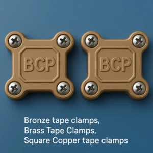
Brass Square Tape Clamps | Bronze Tape Clamps
₹13.40 Add to cart -
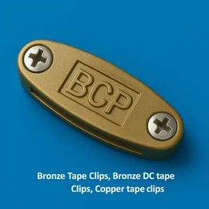
Brass DC Tape Clips, Bronze Tape Clips, DC Clips for Copper Tapes
₹13.40 Add to cart -
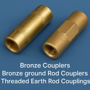
Bronze Ground Rod Couplers, Bronze Threaded Couplers
₹13.40 Add to cart -
Bronze Ground Rod Clamps | Bronze Earth Rod Clamps
₹13.40 Add to cart -
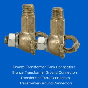
Bronze Transformer Grounding Connectors, Transformer Tank Connectors
₹13.40 Add to cart -
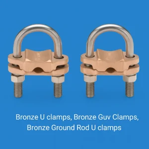
Bronze U Clamps, Bronze U Bolt Clamps, Bronze Grounding Clamps
₹13.40 Add to cart